
Packaging Line Integration Checklist: Interfaces to Confirm Before Ordering
Checklist of mechanical, electrical, signal, communication, safety and utility interfaces to settle before ordering a machine for a packaging line.
Unowned interfaces can cause transfer rework and disputed stop behavior at installation. Before ordering, write down each interface between the new machine and its neighbors: mechanical, electrical, signals, communication, safety, utilities, buffer and documentation. For each, name who defines it, who supplies it and who confirms it.
Applies to: Covers adding a packaging machine to a new or existing line. It does not replace the machine risk assessment, the supplier's drawings, or the detailed engineering of conveyors, networks or safety systems.
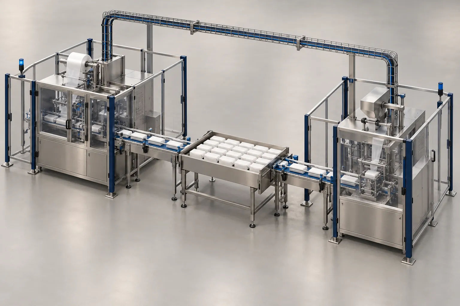
An unowned transfer, signal or stop zone can force rework after delivery. Before ordering, assign an owner and evidence to each interface between the new machine, its neighbors and the plant. Use these suggested roles as a starting point; confirm the actual allocation in the contract.
Swipe sideways to see the other columns. The first column stays visible.
| Interface | Owner to agree | Evidence to deliver |
|---|---|---|
| Mechanical and guarding | Machine/conveyor suppliers with plant engineering | Transfer sketch and reviewed guarding layout |
| Electrical | Plant electrician and machine supplier | Supply details and electrical drawings |
| Signals | Both controls teams or integrator | Signed direction, logic and timing table |
| Communication | Controls and plant IT | Protocol, data map and network approval |
| Safety | Named qualified safety reviewer | Stop-zone plan and validation records |
| Utilities | Plant utilities and supplier | Connection plan and running demand |
| Buffer | Operations and conveyor/integrator owner | Purpose, product condition and full/empty logic |
| Documentation | Each supplier; plant engineering receives | As-built drawings, manuals and backups |
What packaging line integration means
For the announced carton-filling platform, the SIG Neo line review maps supplier statements to interface and verification questions.
Before specifying interfaces, use the automation scope and level guide to decide which stations belong in the project.
A packaging line is the sequence of machines, conveyors and buffers that takes product from the filler or the primary packaging machine through to a closed shipping unit, for example filling and sealing, then inspection, cartoning, case packing and palletizing. Each machine on it can be automated and still run only its own cycle.
Production line integration is the work that makes those machines run as one line. In this checklist, the scope to confirm is the layout, the transfers, the signals and data between machines, the shared safety functions, the utilities and the commissioning tests, plus a named owner for the whole line’s behavior.
The difference from single-machine automation is where the work sits. Automating a machine improves what happens inside its own frame: servo axes, recipes, sensors, its own PLC. Integration deals with what happens between frames: whether the next machine is ready, what a stop on one machine does to the others, and who proves the line works. A line of well-automated machines can still perform poorly as a line when nobody owns those boundaries.
Three integration scopes and what changes at the interfaces
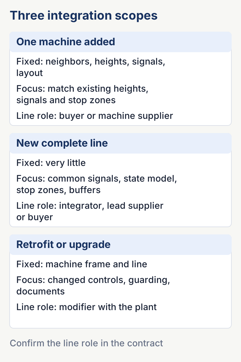
The checklist below applies to every project, but the emphasis changes with the scope. Three common scopes are adding one machine to a running line, building a new line, and retrofitting or upgrading an existing machine or line. Name the scope in the RFQ, because it changes which interfaces are already fixed and who has to adapt to whom.
Swipe sideways to see the other columns. The first column stays visible.
| One machine added to an existing line | New complete line | Retrofit or upgrade of an existing machine or line | |
|---|---|---|---|
| What is already fixed | Neighboring machines, their heights, signals and the floor layout | Very little; layout, controls approach and stop zones are all open | The machine frame and most of the line around it |
| Interfaces to emphasize | Matching the existing transfer heights and orientation; reading the existing signals, which may be undocumented; fitting into the existing emergency stop arrangement | A common signal and data convention for all machines; a line control and state model; the stop zone plan; buffer positions from the start | What the modification changes in controls, guarding and stop behavior; as-built drawings; updated I/O lists and backups |
| Main risk | The new machine is specified against drawings that no longer match the line | Each machine is bought separately and nobody owns the gaps between them | The modified machine no longer matches its original documentation or risk assessment |
| Who usually holds the line role (confirm in the contract) | The buyer’s engineering team or the new machine’s supplier | A line integrator, a lead machine supplier, or the buyer’s own engineering team | Whoever carries out the modification, together with the plant |
| First document to request | A survey of the existing line: heights, signals, stop zones, utilities | An interface responsibility matrix for the whole line | A description of the change and an updated risk assessment |
For retrofits, the modification itself carries responsibilities. ANSI/PMMI B155.1-2023, the US safety standard for packaging and processing machinery, sets out the responsibilities of suppliers, users and modifiers, and clarifies those for existing machinery. Agree in writing who takes the modifier role before work starts, and who updates the risk assessment and the documentation.
Interface priorities by pack type
The same interface list applies to every pack, but some items carry more weight depending on what moves between machines:
- Flexible packs such as pouches and bags. Packs leaving a bagger or pouch machine can arrive flat, tumbled or unevenly spaced. Orientation, spacing for inspection and the transfer onto the next conveyor need the most attention. The VFFS and premade pouch comparison describes how each machine discharges packs.
- Rigid containers such as bottles, jars and tubs. Stability on transfers, guide rails and how containers behave when they queue in a buffer matter most, because containers that tip or mark in accumulation cause stops downstream.
- Cartons and cases. Orientation, counting and grouping before loading, and the hand-off to case sealing and palletizing, decide most of the specification. The cartoner vs. case packer guide covers those steps.
Who can carry out the integration
Buyers searching for packaging line integration companies usually choose between three arrangements. The buyer’s own engineering team integrates machines bought from several suppliers. A lead machine supplier takes responsibility for a section or for the whole line, including other suppliers’ machines. Or an independent line integrator designs and commissions the line around machines it buys or that the buyer selects.
Whichever arrangement you choose, ask the same questions: where the integrator’s scope begins and ends, whether it will produce the interface responsibility matrix and signal tables shown below, how line-level performance is tested at FAT and SAT, and who owns the line’s behavior after handover. Line-level performance commitments, where offered, depend on the conditions written into the contract, so read those conditions rather than the headline. Cost and price factors for integration belong in the total cost of ownership guide.
Takeaway: Name the project scope and modifier role before assigning the interface work.
What an interface is and where it sits
An interface is any point where something passes between two parties: product, signal, power, air, data, or responsibility. The new machine has an interface with the machine before it, the machine after it, the building, the plant network, and the people who run and maintain it.
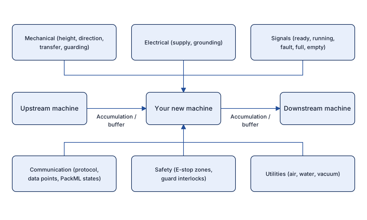
The figure groups the interfaces into six categories around the new machine. Mechanical interfaces cover height, direction, transfer and guarding. Electrical interfaces cover supply and grounding. Signals are ready, running, fault, full and empty. Communication covers protocol, data points and PackML states. Safety covers E-stop zones and guard interlocks, and utilities cover air, water and vacuum. Accumulation or buffer sits between the machines, and documentation ties the package together.
Interface responsibility matrix
Interfaces fail when each party assumes someone else is handling them. The matrix assigns three roles to each: who defines the requirement, who supplies the hardware or data, and who confirms it works. The entries are a starting point to adjust to your project and contract. If a line integrator is involved, that role replaces or splits some of them.
Swipe sideways to see the other columns. The first column stays visible.
| Interface | What to define | Who supplies | Who confirms |
|---|---|---|---|
| Mechanical: transfer height and direction | Product path, transfer height, flow direction, guide dimensions | Machine supplier for the machine side; conveyor supplier or plant for the neighbor | Plant engineering and machine supplier, at drawing review and FAT |
| Mechanical: guarding at transfer | Openings, tunnels, access points, fixed and movable guards | Machine supplier and conveyor supplier for their sections | Plant safety lead with qualified reviewer, per the risk assessment |
| Electrical: supply and grounding | Voltage, phases, frequency, short-circuit rating, disconnect location, grounding scheme | Plant for the supply point; machine supplier for the panel | Plant electrician and machine supplier |
| Signals: handshakes | Signal list, direction, logic level, timing, fault behavior | Both machine suppliers or the integrator | Controls engineers on both sides, at FAT and SAT |
| Communication: network and data | Protocol, addresses, data points, state model, security arrangements | Machine supplier for the machine end; plant IT or line controller owner for the network | Controls engineer and plant IT |
| Safety: emergency stop zones and interlocks | Zone boundaries, which stops affect which machines, restart conditions | Machine suppliers and integrator for the hardware; safety design from the risk assessment | Qualified safety reviewer for the site |
| Accumulation and buffer | Buffer purpose, location, capacity assumption, product condition | Conveyor supplier, integrator or machine supplier | Plant operations and engineering |
| Utilities: air, water, vacuum | Pressure, flow, quality, connection type and location | Plant for the source; machine supplier for the take-off | Plant utilities and machine supplier |
| Documentation | Drawing set, I/O lists, manuals, parameter backups | Each supplier for its scope | Plant engineering, before FAT and before payment milestones |
Mechanical interfaces
Mechanical interfaces cover how product physically moves from one machine to the next. Record the transfer height, the direction of flow, the side of the machine where product enters and leaves, and the support or fixing method. Note any difference between the product orientation that leaves the upstream machine and the one the new machine needs.
Sketch every transfer. Gaps, steps and speed differences at a transfer cause tipping, jamming and damage. Guarding there is a safety topic as much as a mechanical one, because openings that product passes through need to be assessed (see the safety section below).
For fragile product, agree how damage will be observed on each side of a transfer before the trial, so a defect can be traced to a handoff. The cookie flow-wrapper trial checklist shows one way to record it.
Takeaway: Close the drawing review when both sides accept the transfer sketch and product orientation.
Electrical interfaces
Define the supply the plant provides and the supply the machine needs: voltage, phase, frequency, and the disconnecting means at the machine. Specify the grounding scheme and any requirements from the electrical code that applies on your site. IEC 60204-1 covers electrical equipment of machines, and in the US NFPA 79 applies to industrial machinery. Which one applies depends on the market and the machine, and the supplier should state the standard used for the panel.
Takeaway: Have the plant and supplier confirm the supply-to-panel boundary in the drawings.
Signal interfaces
Discrete signals are the oldest and simplest line interface. A pair of machines usually exchanges ready, running, fault, full and empty, though names vary. For each signal, define:
- direction (which machine sends it),
- logic level and whether the signal is normally on or normally off,
- the behavior when the cable is broken or the other machine is off,
- the timing, such as how long a full signal must be present before the upstream machine slows or stops.
Write these in a signal table that both suppliers sign off. “Ready” can mean powered, in automatic, or able to accept product, and those are three different conditions.
Takeaway: Close the signal definition only when both sides accept its meaning, timing and fault behavior.
Communication interfaces
If the machine passes data to a line controller or MES, define the protocol, network addresses, data points and the direction of each. A machine state model such as PackML gives states standard names; ISA-TR88.00.02 describes the PackML machine state model and tags. If you want state data, say so in the RFQ and request the tag list. A machine will not necessarily provide it.
Plant IT should confirm the network arrangements, security conditions and any remote access before the order. The control roles inside the machine are explained in the PLC, HMI and motion control guide.
Takeaway: Keep the approved data map and network owner with the interface record.
Accumulation and buffer
Buffers absorb short stops so that a brief jam on one machine does not immediately stop its neighbors. Decide what the buffer is for, where it sits, and how product behaves in it. Some products accumulate without damage, while others mark, stick, tip or lose orientation. Buffer size and behavior follow from the expected stoppage pattern, which you can observe on your own line. The guide to packaging line bottlenecks shows how to see which machine limits output and how stoppages propagate.
Takeaway: Agree the full/empty response against the product condition expected in the buffer.
Safety interfaces
Safety. A shared emergency stop zone, a guarded transfer opening and a restart interlock between machines each span more than one machine. They come from a risk assessment (ISO 12100 gives the general method) and a review by qualified people, not from copying the arrangement of another line. Planning to bypass a guard or interlock to make integration easier is not acceptable. Servicing a transfer needs a lockout procedure suited to your site.
ISO 13850 covers the design principles of the emergency stop function, and EN 415-10 sets out general safety requirements for packaging machines in the EU. The practical question at the boundary is what the other machines must do when one machine stops, and who decides. Draw the stop zones on the layout, state which stops are local and which are line-wide, and define the restart sequence. Document the result in the safety design and check it in validation.
Takeaway: Treat closure as documented design and qualified validation, not a checked box.
Utilities
List the services the machine needs: compressed air (pressure, flow and quality), water or cooling, vacuum, extraction, steam or inert gas where relevant. For each, state the connection point, the size and type of connection, and who provides the take-off. Ask the supplier for consumption at the rated speed so the plant can check capacity. Air quality classes are described in ISO 8573-1.
Takeaway: Compare stated running demand with the available site supply.
Inspection and downstream equipment
If the line includes inspection, define where it sits and how rejects are handled. The machine vision guide covers vision stations, and the checkweigher and metal detector comparison covers sequence and reject confirmation. Reject devices and locked reject bins are interfaces too, as they connect to signals and to safety and hygiene rules.
For cartoning and case packing, the transfer from primary pack to carton and from carton to case needs the same treatment. The cartoner vs. case packer guide shows how these steps connect.
Takeaway: Include reject confirmation and pack transfers in the same ownership record.
Interface checklist
Copy the checks into your RFQ package. Use one copy of this record per open interface; do not mark a requirement closed without the agreed evidence.
Swipe sideways to see the other columns. The first column stays visible.
| Interface record field | Project entry |
|---|---|
| Interface / requirement ID and revision | |
| Defines / supplies / confirms (named people) | |
| Owner and due date | |
| Evidence file, drawing or test reference | |
| FAT evidence / SAT evidence still pending | |
| Open issue, closure criterion and sign-off |
Mechanical
- Transfer height at the infeed and discharge is defined, with the tolerance the supplier will accept.
- Flow direction, left or right hand, and the machine side for infeed and discharge are drawn on the layout.
- Product orientation and spacing leaving the upstream machine match what the new machine needs.
- Transfer design (plate, belt, chute or gap) is sketched and agreed by both suppliers.
- Conveyor speed matching or speed control between machines is defined.
- Guide rails, side guards and covers at the transfer are assigned to a supplier.
- Floor space, anchoring, operator access and service clearance are marked on the layout.
Electrical
- Supply voltage, phase count, frequency and disconnect location are stated.
- Short-circuit rating and protective device requirements are agreed.
- Grounding and bonding scheme is defined.
- Panel location, cable entry and cable tray routes are drawn.
- Applicable electrical standard for the panel is named by the supplier for your market.
Signals
- Signal list exists with direction, logic level, and wire or terminal references.
- Ready, running, fault, full and empty are each defined in words, not only by name.
- Behavior on cable break, power loss and mode change is stated.
- Timing and delays for full and empty signals are defined.
- Both suppliers have signed off the signal table.
- Reject, inspection and counter signals, if any, are included.
Communication
- Need for line or MES communication is stated: required, optional or not needed.
- Protocol, addresses, data points and update rates are listed.
- State model requirements, including any PackML states, are written down, and the tag list is requested.
- Plant IT has reviewed network security and remote access conditions.
- Time synchronization and data ownership are defined.
- Test method and test data for communication are agreed for FAT and SAT.
Safety
- Machine risk assessment is available or planned, with its scope covering interfaces.
- Emergency stop zones are drawn on the layout, with the effect of each stop on neighboring machines.
- Guard interlock arrangement at transfers and shared access points is described.
- Restart conditions after a stop are defined and reviewed by a qualified person.
- Safety function validation approach and records are requested.
- Lockout and energy isolation points are identified for the new machine and the interfaces.
- Applicable safety standards and the market for the machine are named by the supplier.
Utilities
- Compressed air pressure, flow and quality requirements are stated and checked against the site supply.
- Water, cooling, vacuum and extraction requirements are listed.
- Connection points, sizes and types are marked on the layout.
- Consumption data at the rated speed is supplied.
Accumulation and buffer
- The purpose of the buffer is written down.
- Buffer location and the signals that control it are defined.
- The effect of the buffer on product orientation and condition has been considered.
- Behavior on a full or empty buffer is agreed.
Documentation
- Layout drawing with machine footprints, interfaces and services.
- Electrical drawings, I/O list and signal table.
- Software version list and backup copies.
- Manuals, spare parts list and maintenance schedule.
- Safety documentation as available for your market.
- Responsibilities for the commissioning and the interface tests are in the contract.
Questions to ask suppliers
- Which interfaces does your scope include, and which do you assume the buyer or another supplier will provide?
- Can you supply a signal table and interface drawing for review before the order is placed?
- What does your machine do to the neighboring machines when it stops, and what does it expect in return?
- Which documents do you deliver, in what format, and when?
For an old line without reliable drawings, commission a measured survey and record unverified signals as open items; do not treat an old drawing as an as-built record. If parties dispute responsibility, keep the interface open and obtain a written allocation before authorizing work. For items that can only be demonstrated at SAT, record the factory simulation separately and leave site closure pending with an owner and test condition. These are editorial project-control suggestions, not contract terms.
Limits and on-site verification
A checklist cannot tell you what your line physically looks like. Measure the site and check the drawings against it. Some interface problems appear only with real product, at line speed, in the actual layout.
Plan to verify these points:
- Transfers with actual product, at the speeds you plan to run.
- Handshake signals under start-up, stop, fault and recovery conditions.
- Emergency stop behavior across zones, using a test plan reviewed by a qualified person.
- Utility supply under running conditions, not only on a quiet shift.
The RFQ checklist shows where to put the interface requirements in your request, and the FAT vs. SAT guide describes how to split tests between factory and site. Safety design stays with the machine risk assessment and qualified engineers.
References
- ISO 12100:2010 — Safety of machinery — General principles for design — Risk assessment and risk reduction — ISO
- IEC 60204-1:2016+AMD1:2021 CSV — Safety of machinery — Electrical equipment of machines — Part 1: General requirements — IEC
- ISA-TR88.00.02-2022 — Machine and Unit States: An implementation example of ISA-88.00.01 — ISA
- PackML (Packaging Machine Language) - OMAC — OMAC (Organization for Machine Automation and Control)
- EN 415-10:2014 — Safety of packaging machines — Part 10: General requirements — CEN
- ISO 13850:2015 — Safety of machinery — Emergency stop function — Principles for design — ISO
Update history
- : First published.
- : Added a definition of packaging line integration, a comparison of three integration scopes (one machine added, new line, retrofit), interface priorities by pack type and who can hold the integration role.
- : Added a compact interface ownership overview, copyable issue record and completion criteria; clarified undocumented retrofits and SAT-only evidence; redrew the interface map.
- : Added guidance on observing fragile-product damage on each side of a transfer, with a link to the cookie flow-wrapper trial checklist.
Next steps
Packaging Machine RFQ Checklist: Information Suppliers Need
A reusable blank RFQ template for packaging machines in nine sections, with the reason suppliers need each item and a list of commonly missed details.
Read guide
FAT vs. SAT for Packaging Equipment: Defining Acceptance Criteria
Compare factory and site acceptance tests for packaging machines, and learn how to write acceptance criteria that both buyer and supplier can verify.
Read guide
PLC, HMI and Motion Control: Roles in a Packaging Machine
How the PLC, HMI, motion controller, servo drives, field I/O and safety circuit divide the work in a packaging machine, and what to request from suppliers.
Read guide