
PLC, HMI and Motion Control: Roles in a Packaging Machine
How the PLC, HMI, motion controller, servo drives, field I/O and safety circuit divide the work in a packaging machine, and what to request from suppliers.
In most packaging machines the PLC runs sequence logic and interlocks, the HMI is the operator window for screens, recipes and alarms, and the motion controller with servo drives positions the axes. Safety functions form a separate logical boundary defined by the risk assessment; this does not require every layer to have its own hardware. See the role-overlap section for shared platforms.
Applies to: Covers the control architecture of typical automated packaging machines, such as form-fill-seal, cartoning and case packing equipment. It does not cover control programming, network design or safety system design for a specific machine.
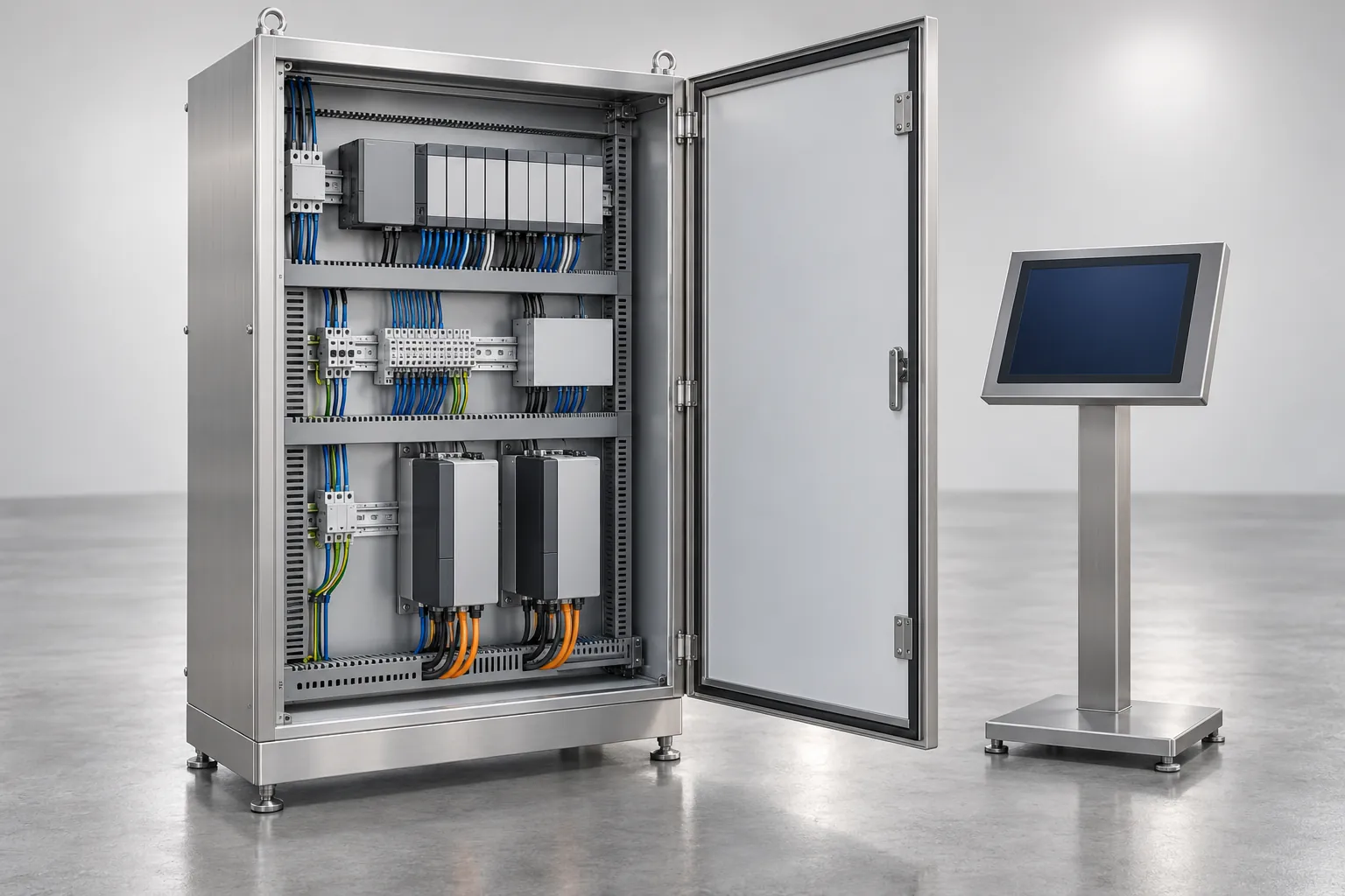
A component list leaves recipe ownership and recovery after a failure unresolved. Assign sequence logic to the PLC, operator interaction to the HMI, and axis movement to motion control; distinguish safety functions logically from standard control, even where hardware is shared. This guide explains the roles and the records to request.
Swipe sideways to see the other columns. The first column stays visible.
| Role | What to confirm at handover |
|---|---|
| PLC | Sequence, interlocks, I/O and program access |
| HMI | Screens, alarms, user levels and recipe location |
| Motion control | Axis parameters, synchronization and backups |
| Safety functions | Risk-assessed functions and validation; logical overlap can share a platform |
How the control layers fit together
Use the packaging automation selection method to separate control features from the degree of automation and the operator work retained.
Most automated packaging machines follow a layered pattern. The layers are logical rather than separate boxes, and on some machines one controller hardware family covers several of them.
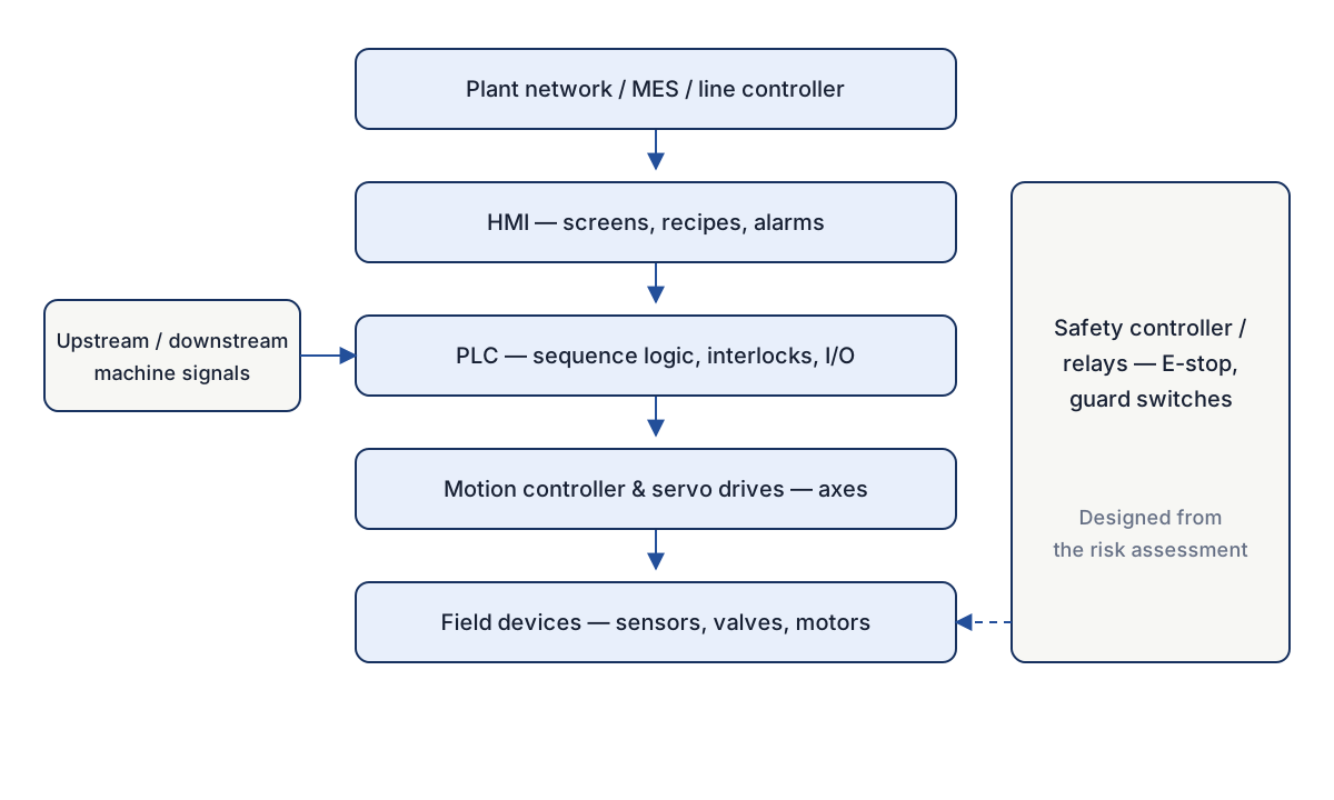
Read from top to bottom, the figure shows the plant network, MES and line controller above the machine. They may send orders or recipes down and receive counts, states and alarms back. The HMI, with its screens, recipes and alarms, is where operators work. The PLC holds the sequence logic, interlocks and I/O, and decides what the machine does and when. The motion controller and servo drives execute coordinated axis movement, and the field devices (sensors, valves, motors) touch the machine and the product. Signals from the upstream and downstream machines connect the machine to its neighbors. Safety functions such as E-stops and guard monitoring are shown in their own logical boundary; their physical implementation is confirmed in the safety design.
Takeaway: Mark where each logical role lives on the actual architecture drawing.
What each element does
A programmable logic controller, or PLC, is an industrial computer built to read inputs, run a repeating program and set outputs. Programming languages used on PLCs are described in IEC 61131-3. In a packaging machine the PLC usually holds the machine sequence: start-up, infeed, forming, filling, sealing, discharge, and the conditions that must be true before each step.
The human-machine interface, or HMI, is the touch screen or panel. It shows machine state, accepts operator commands, selects recipes and lists alarms. Recipe values may be stored in the HMI or another controller; confirm the location. It is a window onto the PLC: a good HMI makes a fault easier to understand, but it does not decide machine behavior.
Motion control moves axes to positions, at speeds, in coordination. A servo axis combines a drive, a motor and position feedback. Some machines run motion inside the PLC; others add a dedicated motion controller. Either way, a buyer needs to know which axes are servo, how they are synchronized, and what happens to a product on a moving axis when a stop occurs.
Field devices include photoelectric sensors, proximity switches, load cells, valves, heaters and contactors. They are the point where electrical signals meet the physical machine. Good components and clear labeling help a technician find a fault faster.
Swipe sideways to see the other columns. The first column stays visible.
| Element | Main job | Typical content | Who normally changes it |
|---|---|---|---|
| PLC | Sequence logic, interlocks, I/O handling | Machine program, timers, fault logic | Controls engineer, under change control |
| HMI | Operator interface | Screens, recipes, alarm text, user levels | Operators for recipe selection; engineers for screen design |
| Motion controller and servo drives | Axis positioning and synchronization | Axis parameters, cam profiles, tuning | Controls or service engineer |
| Field I/O | Sensing and switching | Sensors, valves, motor starters | Maintenance, by replacement |
| Safety controller or relays | Safety functions | E-stop, guard monitoring, safe stop | Qualified safety engineer, under documented review |
| Line or MES interface | Data exchange | Orders, counts, states | Integrator and plant IT with the supplier |
Takeaway: Review delivered functions and access rights alongside the hardware list.
Safety is separate from standard control
Separate here means a safety-function boundary, not a requirement for independent hardware at every layer. Emergency stop and guard monitoring need a defined safety design and validation; a shared controller family may include both standard and safety functions, as the overlap section explains. Confirm the actual implementation in the supplier documentation.
The reason is design intent. Someone can edit, force or restart a standard control program during routine work. A safety function is designed from the machine’s risk assessment, so its behavior is defined, documented and tested. The general method for risk assessment and risk reduction is described in ISO 12100. Design of safety-related control functions is covered by standards such as ISO 13849-1, and electrical equipment of machines is covered by IEC 60204-1 and, in the US, NFPA 79. Which references apply depends on the market and the machine.
Safety. The HMI and the PLC program are not places to adjust safety behavior. A change to a guard, an interlock, an emergency stop or a safety parameter goes back through the risk assessment, ISO 12100 being the general method, and a review by qualified people. Servicing a drive or a cabinet needs a lockout procedure suited to the site.
Takeaway: Send safety-function changes through the documented qualified review.
Machine states and PackML
Packaging machines pass through a limited set of conditions: idle, starting, running, held, stopped, faulted, and so on. A state model gives these conditions agreed names and defines the allowed transitions between them. PackML, from OMAC, is a widely discussed example. ISA-TR88.00.02 describes the PackML machine state model and tags.
A state model exists to make communication easier. If the machine reports “Execute” or “Held” in a defined way, the line controller can read machine status without learning each supplier’s private naming, and operators and maintenance staff share a vocabulary for what the machine is doing.
It has two limits. A state model describes status, not the quality of the machine logic. And whether a given machine uses it, and how fully, depends on what the supplier builds and what you specify. If you want state data on the line network, put the requirement in the RFQ and ask what is delivered: the state list, the tag list, and the mapping to your system.
Takeaway: Specify the required state and tag mapping rather than assuming PackML is delivered.
Communication with the line and MES
A machine usually talks to the outside at two levels. Hard-wired discrete signals between neighboring machines carry simple handshakes such as ready, running, fault, full and empty, and they are easy to trace and test.
Network communication carries richer data: recipe selection, counts, state, alarm lists and sometimes OEE inputs. The protocol, the data points, the owner of the server side and the cybersecurity arrangements all need to be agreed. ISO 22400-2 defines OEE and related indicators, and it is a useful reference when deciding which counts and times the machine should supply.
The packaging line integration checklist lists the signals, protocols and boundaries to confirm between machines before ordering.
Takeaway: Approve the signal list and data map with the integrator and plant IT.
Where the roles overlap in practice
Real machines blur the table above, in several ways.
- A machine may use a PLC with built-in motion, so there is no separate motion controller.
- Recipe values may live in the PLC and be displayed by the HMI, or be stored on the HMI. Where a recipe is stored changes how backup works, and it shapes how recipe loading fits into a format changeover routine.
- A safety PLC may share a hardware family with the standard PLC while remaining a separate logical function.
- Vision systems, checkweighers and printers often bring their own controllers and screens. They report to the main PLC by signals or a network. See machine vision inspection tasks for how an inspection station fits.
- Servo and pneumatic axes often coexist on one machine. The servo vs. pneumatic comparison describes how those choices affect the control scope.
These overlaps are normal. They cause trouble only when the documentation does not say where each function lives.
Takeaway: Include every recipe and parameter storage location in the restore plan.
Information to request from suppliers
Ask for the following in writing, and confirm each item is part of the delivered scope.
- An I/O list with address, description, signal type and wiring reference for every input and output.
- Electrical drawings and a panel layout, in an editable or at least complete form.
- A software version list covering PLC firmware, programming environment, HMI runtime, drive firmware and any safety controller.
- Program ownership and licensing: who holds the source code, whether you receive it, and under what conditions.
- A backup and restore procedure, including a tested backup of the PLC, HMI and drive parameters at handover.
- An alarm list with text, cause, priority and recommended first checks.
- A recipe description: which parameters are stored, how they are edited, and who may edit them.
- Communication protocol documents: protocol, data map, state model or tag list, and the settings of each node.
- Safety documentation: risk assessment summary, safety function descriptions and validation records, as the supplier can supply them for your market.
- User levels and password handling: how access is assigned and how the supplier’s default credentials are removed or changed at handover.
- Remote access arrangements, if any, with the security conditions you require.
These requests belong to acceptance planning. The FAT vs. SAT guide shows where to check them at the factory and again on site.
Takeaway: Put the document set and restore demonstration into acceptance scope.
Checklist for a control review
Copy this handover table and name the person who accepts each record. It is an editorial review aid, not a safety validation protocol.
Swipe sideways to see the other columns. The first column stays visible.
| Record to receive | Owner / evidence / status |
|---|---|
| Architecture and safety-function boundary | |
| I/O list matched to electrical drawing revision | |
| Recipe storage, editable fields and access levels | |
| Source access or license restrictions and support route | |
| PLC / HMI / drive versions and backup locations | |
| Restore test result, failure recovery and approver | |
| Alarm causes and operator instructions | |
| Line signals, data map and required states/tags |
If source code is restricted, record what the owner can restore or modify and who supplies licensed support before accepting the scope. For recipes, name every storage location and include it in the backup procedure. If a restore test fails, keep recovery acceptance open, preserve the test result and ask the responsible controls team to resolve it before relying on that backup. Follow the supplier’s procedure and site approval for any test.
Takeaway: Keep recovery unresolved until the agreed restore test succeeds.
Limits and on-site verification
This guide describes concepts. It cannot say how a specific machine is wired, how it behaves when it stops, or which safety functions it needs.
Verify on the actual machine, with your product and materials:
- That stopping and restarting behave as documented, and that the machine recovers from a fault without confusing operators.
- That recipe changes load the parameters you expect and that wrong selections are caught.
- That network data points show the right values under running, starved, blocked and faulted conditions.
- That backups restore to a working state in a test, not only on paper.
Safety function design and validation belong to the machine risk assessment and qualified engineers. For operation, the supplier’s manual and your site’s procedures are the authority.
Related decisions
Control scope depends on which actuators the machine uses, so read the servo vs. pneumatic comparison alongside this guide. For the connection to the rest of the line, use the interface checklist.
References
- IEC 61131-3:2025 — Programmable controllers — Part 3: Programming languages — IEC
- ISA-TR88.00.02-2022 — Machine and Unit States: An implementation example of ISA-88.00.01 — ISA
- PackML (Packaging Machine Language) - OMAC — OMAC (Organization for Machine Automation and Control)
- ISO 12100:2010 — Safety of machinery — General principles for design — Risk assessment and risk reduction — ISO
- IEC 60204-1:2016+AMD1:2021 CSV — Safety of machinery — Electrical equipment of machines — Part 1: General requirements — IEC
Update history
- : First published.
- : Clarified the logical safety boundary, added a fillable controls handover record and recovery guidance, and made the shared architecture diagram readable on mobile.
Next steps
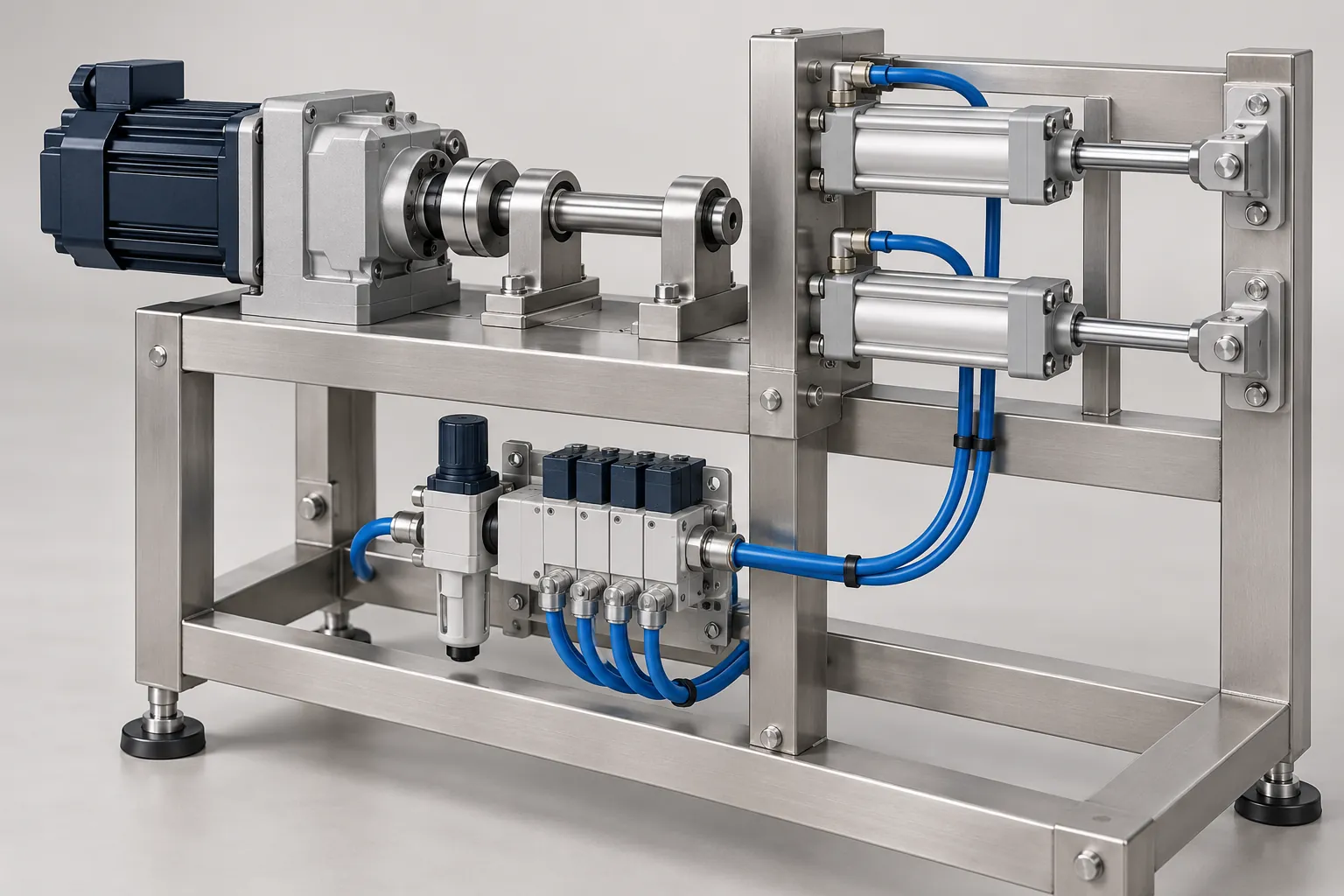
Servo vs. Pneumatic Actuation in Packaging Equipment
Compare servo and pneumatic axes in packaging machines by motion profile, load, changeover, maintenance, utilities and hygiene, plus supplier questions.
Read guide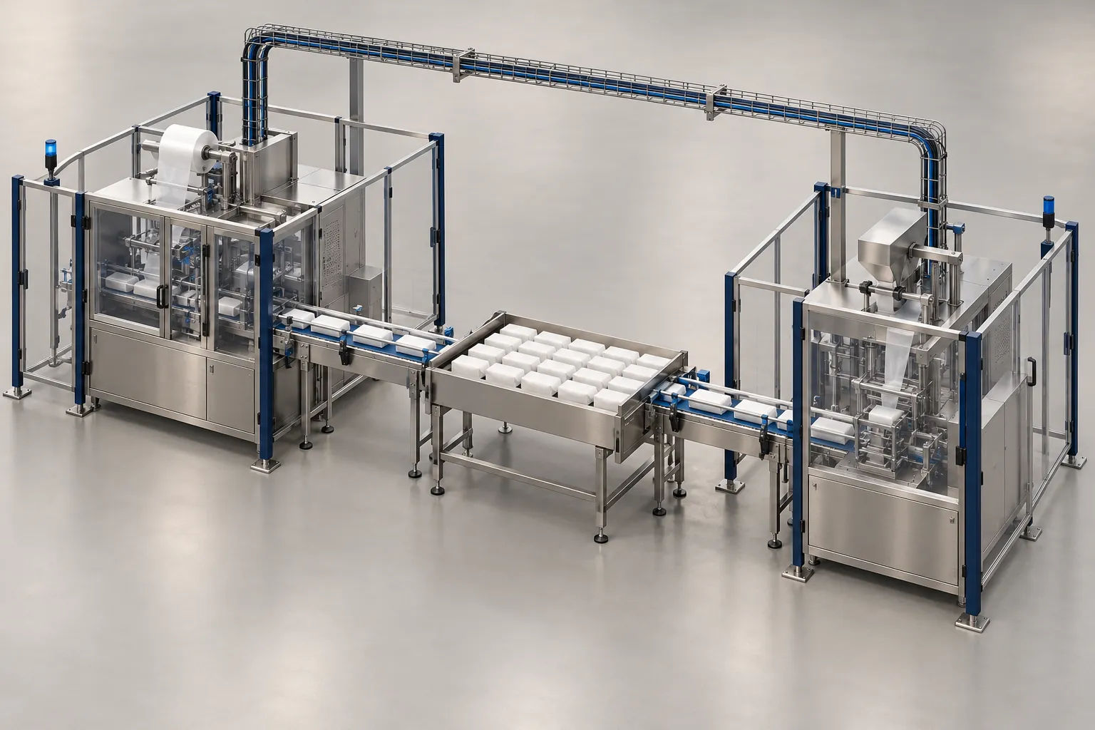
Packaging Line Integration Checklist: Interfaces to Confirm Before Ordering
Checklist of mechanical, electrical, signal, communication, safety and utility interfaces to settle before ordering a machine for a packaging line.
Read guide
Machine Vision for Packaging: Inspection Tasks and Limits
What machine vision can check on a packaging line, what each task needs in samples, lighting and rejects, and where it cannot replace other tests.
Read guide