
Thermoforming Packaging Machine Selection: Flexible PA/PE vs Rigid APET/PE Film, Draw Ratios and Cutting Stations
Specify a horizontal thermoforming packaging machine for 100-300 um PA/PE vs 300-800 um APET/PE film: preheating, plug-assist draw ratios and cutting.
Selecting a horizontal thermoforming packaging machine (rollstock form-fill-seal system) starts with the bottom forming web gauge and draw ratio (cavity depth H divided by minimum pocket width W). Flexible co-extruded PA/PE or PA/EVOH/PE films (100 to 300 um) form with single-side contact heating (90 to 115 degrees C), differential vacuum/air pressure (1 to 3 bar), and guillotine cross-cutting with rotary shear slitters. Rigid APET/PE, RPET/PE, or PP sheets (300 to 800 um) require dual-side top-and-bottom sandwich preheating (115 to 160 degrees C), servo-driven syntactic-foam plug assist whenever the draw ratio H/W exceeds 0.5:1 to prevent 50% to 70% corner wall thinning, and a heavy-duty servo toggle punch-and-die press with radiused corners.
Applies to: Horizontal thermoform-fill-seal (TFFS) rollstock packaging machines and blister packaging machines running flexible PA/PE barrier films or rigid APET/PE, PVC/PE and PP sheets across food, medical device and industrial packaging lines.
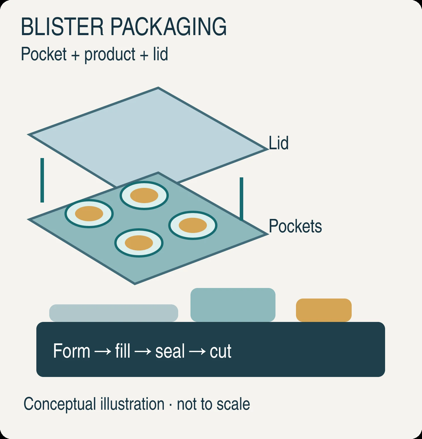
Specifying a horizontal thermoforming packaging machine (widely called a rollstock packaging machine, horizontal thermoform-fill-seal or TFFS system, or wide-web blister packaging machine) requires matching three interdependent engineering variables before requesting supplier quotes: the bottom forming web thickness (100 to 300 um flexible film versus 300 to 800 um rigid sheet), the cavity draw ratio (H / W_min), and the pack severing geometry. A compact entry-level rollstock machine built for 150 um flexible PA/PE vacuum pouches will fail on 500 um APET/PE modified-atmosphere trays, causing severe corner thinning, seal leaks, and unplanned changeover downtime, because it lacks upstream dual-side sandwich pre-heaters, servo plug-assist actuators, decoupled pin-chain side frames, and a 40 to 100 kN toggle punch-and-die press.
Within the broader hierarchy of packaging equipment guides and packaging machine types, European safety standard EN 415-3:2021 and US standard ANSI/PMMI B155.1 classify thermoform-fill-seal systems separately from both premade tray sealers and vertical baggers (covered in the VFFS versus premade pouch comparison). Where a tray sealer accepts pre-molded rigid trays stacked in a denester and only performs filling and lidding, a rollstock thermoformer unwinds flat bottom film, forms pockets in-line, accepts product, seals a top lidding web under vacuum or modified atmosphere packaging (MAP), and cuts individual packs on a single synchronized frame. For narrow-web pharmaceutical tablet cards and cold-form aluminum foil laminates (Alu-Alu), pair this rollstock engineering guide with the blister packaging machine guide.
How a horizontal thermoforming packaging machine builds packs from rollstock
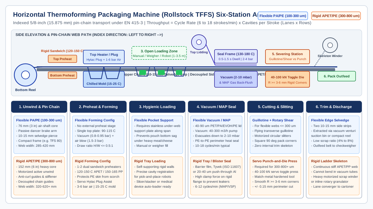
As detailed in Hualian Machinery’s rollstock versus cut-off thermoforming workflow reference and Chlbpack’s station-by-station thermoforming architecture guide, every horizontal rollstock machine indexes two flat film reels through six sequential stations. Twin stainless-steel pin-gripper chains (typically 5/8 inch / 15.875 mm pitch) pierce 10 to 15 mm of each lateral edge of the bottom forming web at the infeed and carry it through the entire machine in intermittent index strokes (L_index = 150 to 600 mm). Because the pin chains bear all longitudinal tensile forces, the heated polymer sheet never stretches or loses pitch registration between the forming die, the sealing chamber, and the cutting knives.
Across OEM frame tiers, such as ULMA’s compact TFS 80 flexible-film thermoformer, ULMA’s mid-to-high output TFS 500 (rated for flexible and rigid film up to 700 um) and high-output washdown TFS 700, MULTIVAC’s R-Series platforms (R105, R145, R245, R535) and recyclable-film R3, and GEA’s PowerPak 5000 and PowerPak PLUS platforms, transitioning from flexible PA/PE film (100 to 300 um) to rigid APET/PE or PP sheet (300 to 800 um) alters the mechanical design of all six stations:
Swipe sideways to see the other columns. The first column stays visible.
| Station number and name | Core mechanical function per index stroke | Flexible film configuration (100 to 300 um PA/PE) |
Rigid sheet configuration (300 to 800 um APET/PE or PP) |
|---|---|---|---|
| 1. Bottom web unwind and pin-chain infeed | Unwinds bottom forming reel (285 to 620 mm width) and pierces 10 to 15 mm side selvedge strips onto twin 5/8 inch pin-gripper chains |
76 mm (3 in) air shaft with passive dancer roller and brake; fits compact 1,670 mm entry frames (such as ULMA TFS 80 or MULTIVAC R105) |
152 mm (6 in) heavy-duty core chuck with motorized active unwind, anti-curl rollers, and reinforced chain guides decoupled from die loads (as on MULTIVAC R3 and R245) |
| 2. Pre-heating and forming station | Softens polymer web above glass transition (Tg) and stretches cavities into a water-cooled aluminum mold (15 to 25 degrees C for APET/PVC; 50 to 80 degrees C for PP) |
Single top contact heating plate inside the forming tool (90 to 115 degrees C); forms via vacuum (0.8 to 0.95 bar) and compressed air (1.5 to 3 bar) without external pre-heaters |
1 or 2 upstream dual-side (top-and-bottom sandwich) contact pre-heating stages (120 to 150 degrees C for APET; 150 to 165 degrees C for PP) plus servo syntactic-foam plug assist and 3 to 6 bar air |
| 3. Open hygienic loading zone | Provides a 1.0 to 3.5 m open horizontal conveyor span where manual operators, multihead weighers, slicers, piston fillers, or robots load product |
Requires a continuous stainless under-web support plate beneath the pin chains so thin formed pockets do not sag under product weight | Self-supporting rigid tray walls hold exact cavity centerlines for high-speed robotic pick-and-place, slicer stackers, or medical device loaders |
| 4. Top lidding unwind and vacuum/MAP sealing chamber | Unwinds printed or clear barrier lidding (40 to 90 um), registers eye-marks, evacuates chamber air (40 to 300 m3/h pump down to 2 to 10 mbar), back-flushes MAP gas, and heat-seals flanges (130 to 180 degrees C, 0.5 to 1.5 s dwell) |
Standard pneumatic or knee-lever lower chamber closing against upper heated seal plate (2 to 3 bar clamp pressure); PE-to-PE fusion or peelable seal |
High-tonnage servo or toggle chamber clamping to flatten thick rigid flange ribs and prevent channel leakers; supports barrier film, medical Tyvek (ISO 11607), or 20 to 40 um push-through aluminum foil |
| 5. Cross-cutting and longitudinal slitting or punching | Divides the continuous multi-cavity web matrix (for example, 2x2, 3x2, or 4x3 packs per stroke) into individual finished units |
Flying transverse guillotine blade (straight, zig-zag, or perforation) paired with motorized rotary circular shear slitting knives | Heavy-duty servo toggle match-metal punch-and-die press (40 to 100 kN force) stamping complete perimeter contours with radiused corners (R >= 3 to 6 mm), or star corner-punch plus rigid shear |
| 6. Edge-trim extraction and pack discharge | Strips the two 10 to 15 mm pin-chain selvedge ribbons (or full ladder skeleton) and transfers finished packs to inline inspection |
Flexible edge strips are sucked directly into a vacuum venturi collection bin or wound onto compact twin scrap spools | Stiff rigid APET/PP ladder skeletons cannot bend through vacuum tubes; requires heavy-duty motorized scrap winders or an inline rotary skeletal granulator |
Machine output on a horizontal thermoformer is governed by the product of cycle frequency and die cavity count:
Output (packs/min) = Cycle Rate (strokes/min) * Cavities per Stroke (N_lanes * N_rows)
For example, a 3x2 cavity die (6 cavities per stroke) cycling at 12 strokes/min delivers 72 packs/min. Because vacuum evacuation (0.5 to 1.2 s), MAP gas back-flushing (0.3 to 0.8 s), heat-seal dwell (0.6 to 1.2 s), and polymer cooling (0.5 to 2.5 s) occur in parallel across stations during every index dwell, thickening the bottom web from 150 um flexible PA/PE (12 to 18 strokes/min) to 550 um rigid APET/PE (7 to 11 strokes/min) lengthens heating and cooling dwell times and directly shifts the pacing rate used in packaging line OEE calculation and bottleneck analysis.
Flexible PA/PE film (100-300 um) vs rigid APET/PE sheet (300-800 um): material and thermal mechanics
Selecting between a flexible-only rollstock machine and a rigid-capable thermoformer starts with the polymer architecture and thermal diffusivity of the bottom forming web. As documented in Hualian Machinery’s thermoforming polymer and barrier film engineering reference, flexible thermoforming webs are co-extruded 7-, 9-, or 11-layer laminates built around a balanced thickness ratio:
- Outer structural and thermoforming layer (
15% to 20%of gauge): Polyamide (PA6orPA6/66nylon), providing high biaxial tensile elongation without pinholing, surface abrasion resistance, and thermal stability against the forming heater plate. - Tie layers (
~5%each): Maleic-anhydride-grafted polyolefin adhesive resins bonding polarPAandEVOHlayers to non-polar polyolefin layers. - Core gas-barrier layer (
5% to 10%of gauge): Ethylene vinyl alcohol (EVOH), providing oxygen barrier (OTR < 0.5 to 1.7 cc/[m2*day*atm]unformed) for modified-atmosphere and vacuum meat, cheese, fish, and ready-meal packs. - Inner heat-sealant layer (
55% to 70%of gauge): Linear low-density polyethylene (LLDPE), metallocenePE(mLLDPE), or cast polypropylene (CPP), providing hermetic perimeter fusion or controlled peelability (verified per ASTM F88 in the film and machine compatibility guide).
Modern resin orientation allows converters to down-gauge flexible webs without sacrificing deep-draw puncture protection. In SÜDPACK’s Multifol Extreme thermoforming film release, a high-tenacity 150 um PA/PE bottom web replaces conventional 200 um flexible thermoforming films on standard rollstock lines, cutting packaging weight by 25% to 30% while resisting bone and fin puncture in vacuum and MAP fish packaging.
By contrast, rigid rollstock packaging relies on amorphous polyethylene terephthalate (APET), post-consumer recycled RPET, rigid polyvinyl chloride (PVC), high-impact polystyrene (HIPS), or semi-crystalline polypropylene (PP) sheets from 300 to 800 um (and up to 1,000 to 1,200 um on heavy industrial frames). For food MAP trays, a 350 to 650 um APET structural sheet is laminated with a 30 to 50 um inner PE (or EVOH/PE) sealant film (APET/PE). In healthcare and medical device sterile barrier systems (validated to ISO 11607), Amcor’s AmSecure mono-APET rigid rollstock replaces traditional PETG on horizontal thermoformers, delivering optical clarity, impact rigidity, and ethylene-oxide or gamma sterilization compatibility while meeting Association of Plastic Recyclers (APR) mono-material recycling criteria.
Why rigid APET/PE and PP require dual-side sandwich pre-heating
Polymers have low thermal conductivity (k ≈ 0.15 to 0.24 W/[m*K]). On a 150 um (0.15 mm) flexible PA/PE web, heat from a single top contact plate inside the forming tool (90 to 115 degrees C) conducts through the entire thickness in 0.8 to 1.2 seconds.
Because conductive heat diffusion time scales with the square of sheet thickness (t_diffusion ~ d^2 / alpha), heating a 600 um (0.60 mm) APET/PE rigid sheet takes roughly 16 times longer than a 150 um film if heated from one side only. Worse, in an APET/PE laminate, the thin inner PE sealant skin faces upward toward the product side and melts at Tm ≈ 105 to 120 degrees C, whereas the thick structural APET core must be heated to 120 to 150 degrees C (well above its glass transition Tg ≈ 75 to 80 degrees C) to stretch cleanly without whitening or spring-back. Applying 150 degrees C from a single top heater scorches and sticks the PE sealant layer before heat ever reaches the bottom of the APET sheet.
To overcome this thermal bottleneck, rigid rollstock thermoformers add 1 or 2 upstream dual-side (top-and-bottom sandwich) contact pre-heating stations ahead of the forming die:
- Asymmetric sandwich temperature profiling: The bottom pre-heater plates contact the bare structural
APETside at130 to 150 degrees C, while the top pre-heater plates (coated with non-stick PTFE) contact thePEsealant side at a controlled105 to 120 degrees C. - Multi-step thermal soak: Indexing the sheet through one or two upstream pre-heat strokes allows heat to soak into the core of the
300 to 800 umsheet over two or three machine cycles before the web enters the water-cooled forming mold, keeping cycle speed at8 to 12 strokes/min. - Recyclable mono-APET and PP frame stabilization: Semi-crystalline
PP(150 to 170 degrees Cforming window) and mono-APEThave much narrower thermoelastic windows thanPA/PE. As documented in MULTIVAC’s R3 technical specification for recyclable mono-materials, preventing wave distortion along tray flanges requires all-over uniform heating plates, individually adjustable pin-chain guides, and a frame architecture that decouples film advance from forming and sealing forces so the side frames carry100%of the die weight without transmitting mechanical vibration into the softened web.
Swipe sideways to see the other columns. The first column stays visible.
| Engineering parameter | Flexible forming film (PA/PE, PA/EVOH/PE) |
Rigid forming sheet (APET/PE, RPET/PE, PP) |
Medical & pharma blister web (APET, PETG, PVC/PVDC) |
|---|---|---|---|
Nominal unformed web gauge (t_0) |
100 to 300 um (4 to 12 mil); down-gauged high-tenacity grades at 120 to 180 um (e.g., SÜDPACK Multifol Extreme 150 um) |
300 to 800 um (12 to 32 mil); up to 1,000+ um on heavy industrial frames |
200 to 600 um (8 to 24 mil) for thermoformed trays and push-through blister cards |
| Unwind reel core ID and tension control | 76 mm (3 in) core; passive dancer roller and pneumatic brake |
152 mm (6 in) core; motorized unwind with active tension control (e.g., GEA PowerPak 5000) and anti-curl rollers |
76 mm or 152 mm core; low-inertia dancer for narrow-web registration accuracy |
Glass transition (Tg) and forming temperature window |
PA6 Tg ≈ 47 to 50 degrees C; single-side contact heating at 90 to 115 degrees C |
APET Tg ≈ 75 to 80 degrees C, forming at 120 to 150 degrees C; PP forming at 150 to 170 degrees C |
PVC forming at 110 to 130 degrees C; APET / PETG (Amcor AmSecure) at 120 to 145 degrees C |
| Pre-heating station hardware | None (heated inside the forming station during index dwell) | 1 or 2 upstream dual-side (top-and-bottom sandwich) contact or zoned matrix pre-heaters | 1 dual-side contact or ceramic matrix pre-heater (or cold-form PTFE stamp for Alu-Alu) |
| Forming pressure and plug assist | Vacuum (0.8 to 0.95 bar) + air (1.5 to 3 bar); plug assist only on ultra-deep draws (H/W > 0.6:1) |
Compressed air (3 to 6 bar) + mandatory servo syntactic-foam plug assist (Hytac) whenever H/W > 0.45:1 |
Compressed air (4 to 6 bar) + multi-cavity syntactic-foam or PTFE plug assist for uniform barrier |
| Mold cooling circuit setpoint | 15 to 20 degrees C chilled water loop through aluminum mold base |
15 to 25 degrees C for amorphous APET/PVC (prevents crystallization haze); 50 to 80 degrees C for PP |
15 to 22 degrees C closed-loop chiller circuit for dimensional stability |
| Severing / cutting station hardware | Flying transverse guillotine knife + motorized rotary circular shear slitters | Servo toggle match-metal punch-and-die press (40 to 100 kN) or star corner-punch + heavy rigid shear |
Precision hardened-steel perimeter punch-and-die press with batch embossing and rounded corners |
| Typical production cycle speed | 10 to 18 strokes/min (vacuum/MAP); 15 to 25 strokes/min (non-vacuum) |
6 to 12 strokes/min (MAP/vacuum); 4 to 8 strokes/min (vacuum skin pack VSP) |
12 to 25 strokes/min (wide medical rollstock); 30 to 80+ strokes/min (narrow pharma blister) |
| Representative OEM machine platforms | ULMA TFS 80 / TFS 200, MULTIVAC R105, GEA PowerPak 1000 | ULMA TFS 500 (up to 700 um) & TFS 700, MULTIVAC R3 / R245 / R535, GEA PowerPak 5000 & PLUS |
MULTIVAC R245 Medical / RX 4.0, ULMA TFS 400/500 Medical, Sepha EZ Blister |
Draw ratio math, corner wall thinning and when servo plug assist becomes mandatory
When a clamped flat rectangle of heated polymer is blown into a three-dimensional mold cavity of length L, width W, and depth H, conservation of polymer volume forces the walls and bottom corners to thin. Packaging engineers quantify forming severity using two geometric ratios:
- Linear Draw Ratio (
LDR, or depth-to-width ratio):LDR = H / W_minwhereHis the formed cavity depth (mm) andW_minis the minimum horizontal cavity width (mm). - Areal Draw Ratio (
ADR, or surface-area stretch ratio):ADR = A_formed / A_footprint = (W * L + 2 * H * [W + L]) / (W * L) = 1 + (2 * H * [W + L]) / (W * L)whereA_footprint = W * Lis the unformed flat film area clamped inside the mold rim andA_formedis the total interior surface area of the formed tray (bottom panel plus four vertical sidewalls). - Theoretical Mean Formed Wall Thickness (
t_mean):t_mean = t_0 / ADRwheret_0is the initial unformed web gauge (um).
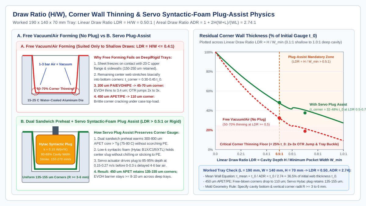
In real thermoforming, wall thickness never equals t_mean uniformly across the tray. During free-blown vacuum or compressed-air forming (without a mechanical plug), the hot polymer sheet bows downward like a soap bubble. As soon as the expanding bubble touches the upper flange and upper sidewalls of the water-cooled aluminum mold (15 to 25 degrees C), that polymer freezes on contact and locks at 75% to 85% of its initial thickness t_0. Only the remaining unfrozen ring of film near the bottom continues stretching into the 90-degree bottom corners and cavity edges.
As quantified in Hualian Machinery’s thermoforming physics and Buntinx et al. (Polymers 2014) barrier-thinning analysis, free-blown biaxial stretching thins the bottom corners by 50% to 70% (t_corner ≈ 0.30 * t_0 to 0.45 * t_0) whenever LDR = H / W_min reaches or exceeds 0.5:1:
- Barrier degradation in flexible and EVOH webs: When a
166 to 293 ummulti-layer barrier film is deep-drawn without plug assist, flange edges retain150 to 250 umwhile the bottom corners thin down to21 to 26 um(or45 to 70 umon a200 umweb). Because theEVOHbarrier core thins proportionally (from15 umdown to3.4 to 5.2 um) and suffers polymer chain micro-voiding under high biaxial strain, container oxygen transmission rate (OTR) jumps by2x to 3x(rising from0.48-1.7 cc/[m2*day*atm]before forming to1.0-3.5 cc/[m2*day*atm]after forming), cutting MAP shelf life short. - Structural buckling in rigid APET/PE trays: When a
300 umrigid sheet thins to90 to 120 umat the bottom corners (or a450 umsheet thins to110 um), the brittle amorphous corners crack during cold-chain drop testing or buckle under secondary case-packing top load.
Worked draw-ratio and corner-thickness calculation (190 x 140 mm MAP tray)
To verify whether a candidate machine requires servo plug assist during packaging machine RFQ specification, evaluate an assumed standard retail meat or ready-meal tray footprint of length L = 190 mm and width W = 140 mm (A_footprint = 190 * 140 = 26,600 mm2) across three cavity depths (H = 35 mm, 70 mm, and 98 mm):
Swipe sideways to see the other columns. The first column stays visible.
Assumed tray geometry (L = 190 mm, W = 140 mm) |
Linear Draw Ratio (LDR = H / W) |
Areal Draw Ratio (ADR) |
Theoretical mean wall (t_mean = t_0 / ADR) |
200 um PA/EVOH/PE corner gauge (Free-Blown, no plug) |
450 um APET/PE corner gauge (Free-Blown vs Servo Plug Assist) |
Resulting barrier and structural outcome |
|---|---|---|---|---|---|---|
Shallow tray: H = 35 mm (A_formed = 49,700 mm2) |
0.25 : 1 |
1.87 : 1 |
53.5% of t_0 (107 um for 200 um; 241 um for 450 um) |
105 to 120 um (EVOH ≈ 8.5 um) |
Free: 215 to 235 um / Plug: 230 to 250 um |
Pure vacuum/air forming (1.5 to 3 bar) passes both OTR and top-load crush limits without plug assist |
Medium-deep tray: H = 70 mm (A_formed = 72,800 mm2) |
0.50 : 1 (Threshold) |
2.74 : 1 |
36.5% of t_0 (73.0 um for 200 um; 164.2 um for 450 um) |
55 to 70 um (EVOH ≈ 4.5 um; 2.2x OTR rise) |
Free: 110 to 130 um (Fail) / Servo Plug: 140 to 158 um (Pass) |
Mandatory threshold (H/W = 0.5:1): rigid 450 um APET/PE requires servo syntactic-foam plug assist to prevent corner cracking |
Deep tray: H = 98 mm (A_formed = 91,280 mm2) |
0.70 : 1 |
3.43 : 1 |
29.1% of t_0 (58.3 um for 200 um; 131.1 um for 450 um) |
32 to 45 um (EVOH ≈ 2.8 um; 3.0x OTR spike & pinholes) |
Free: 75 to 95 um (Severe buckle) / Servo Plug: 115 to 130 um (Requires 550 um web) |
Requires both servo plug assist (85% width, 92% stroke depth) and up-gauging rigid sheet to 550-600 um (or 250 um flexible with plug) |
Note: Assumed example calculations above use ADR = 1 + 2H(W+L)/(WL) for a 190 x 140 mm rectangular cavity with corner radius R = 5 mm.
Specifying servo syntactic-foam plug assist (Hytac) and mold radii
Whenever LDR = H / W_min > 0.5:1 (or for any rigid APET/PE and PP tray deeper than 35 to 40 mm), specify a closed-loop servo-driven plug-assist assembly (combining the motion control principles in the servo versus pneumatic actuation guide):
- Syntactic-foam plug material (
k ≈ 0.12 to 0.23 W/[m*K]): Never use bare aluminum plugs on thin or clearAPET/PEtrays; metal conducts heat out of the sheet on contact (k ≈ 160 to 200 W/[m*K]), freezing a thick, hazy “chill mark” ring on the tray floor. Specify syntactic foam (hollow glass microspheres embedded in a toughened epoxy or copolymer matrix, such asHytac B1Xfor generalAPET/PP,Hytac C1RorXTLfor high-clarityAPET, or PTFE-filled syntactic foam to prevent sticking against hotPEsealant layers). - Plug-to-cavity clearance and corner radii: Machine the plug footprint to
80% to 88%of the mold cavity opening (leaving an annular side clearance of1.5x to 2.5xinitial sheet gauge plus draft angle). Design both the mold bottom corners and plug bottom radii atR >= 3 to 6 mm; sharp1 mmradii act as stress concentrators that tearEVOHbarrier layers. - Servo velocity and air-blow delay profiling: Drive the plug downward at a controlled
0.15 to 0.27 m/s(150 to 270 mm/s) to85% to 95%of full cavity depth, carrying the thick central web disk down toward the bottom corners before triggering the3 to 6 barforming air valve after a programmable0 to 0.30 seconddelay. Where corner thinning persists on rectangular trays, combine servo plug assist with multi-zone or pixel-matrix pre-heating (such as5 x 5 mmceramic heating zones) to keep flange regions cooler (+10 to 15 degrees Cstiffer) so they feed material into the corners during plug descent.
Selecting the cutting station: guillotine and rotary shear slitters vs servo punch-and-die presses
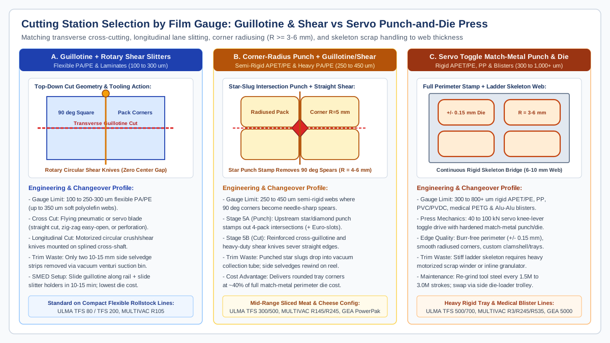
A common capital-project failure occurs when a plant buys a rollstock thermoformer fitted only with flexible-film knives and later attempts to run 400 um APET/PE rigid trays. As explained in Hualian Machinery’s rollstock cut-off station comparison and ULMA’s TFS 80 versus TFS 500/700 specifications, the severing method at Station 5 is dictated by bottom web thickness, corner safety, and skeleton waste handling:
- Flying Cross-Cut Guillotine + Motorized Rotary Circular Shear Slitters (
100 to 300 umflexible film):- Mechanics: A pneumatic or servo-driven transverse guillotine blade slices across the web between rows while motorized circular upper and lower shear knives slit the web longitudinally between lanes.
- Pack geometry and limits: Because the straight transverse cut intersects the straight longitudinal slits at
90 degrees, every pack has square90-degreecorners and zero internal web skeleton between lanes (only the two10 to 15 mmpin-chain edge strips are trimmed and sucked into a vacuum venturi bin). Above300 umin stiffAPETorPVC, circular shear blades chip, leave white stress fractures along the cut edge, and produce needle-sharp90-degreeplastic corners that puncture adjacent vacuum packs or lacerate handlers’ fingers.
- Corner-Radius Star Punch + Cross Guillotine + Longitudinal Shear (
250 to 450 umsemi-rigid webs):- Mechanics: Adds an upstream compact vertical punch station (Station 5A) fitted with star- or diamond-shaped punches placed at every four-pack intersection (and optional Euro-slot hang-hole punches), followed by a reinforced cross-guillotine and heavy-duty circular shear knives (Station 5B).
- Pack geometry and limits: The star punch stamps out a small diamond slug at each intersection, giving all four meeting tray corners a smooth
R = 4 to 6 mmradius before the straight transverse and longitudinal cuts pass through the punched hole. This hybrid layout delivers safe, rounded retail tray corners at roughly40%of the tooling cost of a full perimeter punch-and-die press.
- Heavy-Duty Servo Toggle Match-Metal Punch-and-Die Press (
300 to 1,000+ umrigidAPET/PE,PP, and medical blisters):- Mechanics: Uses a
40 to 100 kNservo-driven knee-lever toggle press beneath the web driving a hardened tool-steel punch through a matched upper cutting die plate with0.01 to 0.03 mmradial clearance. - Pack geometry and limits: Stamps out the complete closed perimeter of every tray or blister card simultaneously to
+/- 0.15 mmtolerance, supporting smooth radiused corners (R >= 3 to 6 mm), contoured clamshells, or multi-cavity medical trays. Because the punch cuts a closed loop around each pack, a continuous6 to 10 mmbridge grid (ladder skeleton) remains and must be wound onto a motorized heavy-duty overhead scrap spindle or fed into an inline rotary granulator.
- Mechanics: Uses a
Swipe sideways to see the other columns. The first column stays visible.
| Cutting station parameter | Option A: Guillotine + Rotary Shear Slitters | Option B: Star Corner-Punch + Guillotine/Shear | Option C: Servo Toggle Match-Metal Punch & Die |
|---|---|---|---|
| Compatible bottom web gauge | 100 to 250-300 um flexible PA/PE (up to 350 um soft polyolefins) |
250 to 450 um semi-rigid APET/PE and heavy PA/PE webs |
300 to 800+ um rigid APET/PE, RPET/PE, PVC/PE, PP, and Alu-Alu |
| Pack corner and perimeter profile | Square 90-degree corners; straight rectangular edges only (optional zig-zag easy-open cross blade) |
Smooth radiused corners (R = 4 to 6 mm) with straight rectangular sidewalls; optional Euro-slot punch |
Full custom 2D perimeter contour, radiused corners (R >= 3 to 6 mm), thumb peel tabs (+/- 0.15 mm accuracy) |
| Skeleton and trim waste handling | Two 10 to 15 mm side selvedge strips (4% to 8% web scrap) extracted via vacuum venturi tube |
Small punched star slugs vacuum-extracted into bin + side selvedge strips wound on scrap reels (6% to 10% scrap) |
Continuous stiff ladder skeleton web (12% to 22% web scrap) wound on heavy motorized spindle or inline chopper |
| Format changeover work (SMED) | Slide cross-cutter along rail for index length; slide rotary knife holders on splined shaft (10 to 15 min) |
Reposition star-punch dies to match lane/row pitch + adjust guillotine and slitter spacing (15 to 25 min) |
Exchange complete matched punch-and-die cartridge using a side die-loader trolley (15 to 25 min) |
| Blade / die maintenance interval | Replace inexpensive guillotine blade and circular shear rings every 3 to 6 months in-house |
Re-sharpen star punches and guillotine knives every 1.0M to 2.0M cycles |
Precision surface-grind matched tool-steel punch and die every 1.5M to 3.0M strokes (3 to 6 months) |
| Relative tooling capital per SKU | Lowest (1.0x baseline; universal across multiple advance lengths) |
Moderate (2.0x to 2.8x baseline; star punches shared across matching radii) |
Highest (4.5x to 8.0x baseline; dedicated hardened punch-and-die set per tray footprint) |
Tooling changeover (SMED), cooling circuits and line OEE integration
Because a horizontal thermoforming packaging machine contains heated forming plates, water-cooled mold bases, a vacuum/MAP sealing chamber, and cutting dies, poorly engineered format changeovers can stall a line for 60 to 120 minutes, directly eroding Availability (A) in your packaging line OEE calculation. Applying Single-Minute Exchange of Die (SMED) principles alongside the packaging format changeover checklist separates thermoformer tool changes into two distinct scopes:
- Scope 1: Cavity depth change only (same
L x Wfootprint and index stroke): When switching from a35 mmshallow meat tray to a70 mmdeep family pack that shares the same190 x 140 mmflange perimeter and2x2matrix, the top sealing frame, lower sealing chamber, and Station 5 cutting dies remain untouched. Technicians simply unbolt or unclamp the drop-in aluminum bottom cavity insert plates and swap the quick-release syntactic-foam plug tips inside Station 2, completing the mechanical swap in10 to 15 minutes. - Scope 2: Full footprint, lane count, or flexible-to-rigid conversion:
Traditionally, changing the cavity footprint (
L x W) required lifting a100 kgupper sealing/forming assembly with an overhead hoist and draining the mold cooling water circuit, a slow operation that spilled water into the hygienic frame and risked microbial or seal-flange contamination. As demonstrated on MULTIVAC’s R3 quick-change tooling system, modern rollstock designs keep the cooling water circuit permanently closed inside the base bolster while technicians slide out a lightweight20 kgformat plate after releasing captive fasteners. On heavy wide-web machines such as ULMA’s TFS 500 and TFS 700 and GEA’s PowerPak 5000, wheeled side die-loader trolleys align with the open lateral frame doors to roll heavy forming, sealing, and punch-and-die cartridges in and out horizontally while the HMIChangeover Assistchecklist recalls pre-heat temperatures, servo plug stroke curves, vacuum/MAP pressure targets, and eye-mark offsets in20 to 35 minutes.
Swipe sideways to see the other columns. The first column stays visible.
| Changeover scope on rollstock thermoformer | Forming station (Station 2) work | Sealing station (Station 4) work | Cutting station (Station 5) work | Target SMED internal stopped window |
|---|---|---|---|---|
1. Pocket depth change (H only; identical L x W flange) |
Swap drop-in aluminum cavity bottom inserts / spacer plates and syntactic-foam plug tips; recall servo plug depth in HMI | None (seal flange perimeter and upper heated frame unchanged) | None (pack length, lane width, and corner contour unchanged) | 10 to 15 minutes (cooling water circuit stays closed) |
2. Index stroke / pack length change (L changes; same lane width W) |
Slide modular forming die insert (20 kg format plate) into closed-loop cooling base |
Slide sealing chamber to new laser-scale rail position; swap seal frame plate (20 kg) |
Slide cross-cut guillotine along frame rails and update servo index length in HMI (or swap punch die) | 18 to 25 minutes (using dry-break or closed-loop water manifolds) |
3. Full matrix + flexible-to-rigid conversion (e.g., 180 um PA/PE 3x2 to 500 um APET/PE 2x2) |
Enable upstream dual sandwich pre-heaters; roll in rigid plug-assist forming die via side trolley; load 152 mm rigid reel |
Swap sealing chamber insert and upper seal frame via side trolley; increase clamp force and dwell recipe | Roll out guillotine/slitter module or engage servo toggle match-metal punch-and-die press; thread skeleton winder | 25 to 35 minutes (plus 10 min external pre-soak of sandwich heaters) |
Questions to ask suppliers and rollstock FAT/SAT verification checklist
When preparing your specification package with the packaging machine RFQ checklist and scheduling acceptance runs under the FAT versus SAT packaging equipment guide and seal defect investigation checklist, require written engineering responses to five questions:
- Web width, index stroke, and frame expandability: What exact bottom web width (
mm), index advance stroke (mm), and maximum forming depth (mm) is the quoted frame configured for, and how many open frame modules remain for adding a second sandwich pre-heater, an automatic loader, or a corner-rounding punch later? - Pre-heating and plug-assist specification: At our maximum draw ratio (
LDR = H / W_min) and maximum rigid sheet gauge (um), how many dual-side sandwich pre-heating stages are included, what syntactic-foam plug grade (Hytac B1X,C1R, or PTFE-filled) is supplied, and is the plug axis driven by a closed-loop servo motor with programmable velocity and air-blow delay? - Guaranteed minimum corner wall thickness and OTR: Across all cavities of the proposed multi-lane die (
N_lanes x N_rows), what minimum residual bottom-corner wall thickness (um) and formed-pack oxygen transmission rate (cc/[pack*day]) does the supplier guarantee on our specifiedPA/EVOH/PEorAPET/PEweb? - Cutting station edge quality and safeguarding: Which severing architecture is quoted (guillotine + shear, star corner-punch + shear, or servo toggle match-metal punch-and-die), what is the guaranteed blade/die re-grind interval in strokes, and how are tunnel guards and interlocked doors engineered to comply with EN 415-3 and ANSI/PMMI B155.1?
- Closed-loop cooling changeover: Can operators exchange forming and sealing format plates without draining the chilled water circuit, and are wheeled die/reel trolleys included for components exceeding
20 to 25 kg?
Copy and execute this verification checklist during your Factory Acceptance Test (FAT) and Site Acceptance Test (SAT):
- Measure unformed bottom web thickness (t_0) and COF (ASTM D1894), then section formed cavities from all four outer corners and the center of the die matrix (N_lanes x N_rows) to verify with a ball-micrometer or ultrasonic hall-effect gauge that bottom corner thickness meets the minimum specification (at least 35 to 45 um on flexible barrier film and 130 to 150 um on rigid trays) without chill marks.
- On rigid APET/PE laminates (300 to 800 um), inspect the inner PE sealant surface after dual-side sandwich pre-heating to confirm zero thermal scorching, sticking, or flange wave distortion prior to sealing.
- Verify vacuum evacuation time (mbar reached per cycle) and MAP residual headspace oxygen (below 0.5% O2 or product-specific target) across 50 consecutive cycles at the guaranteed nameplate stroke rate (strokes/min multiplied by cavities/stroke).
- Perform destructive peel and burst testing (ASTM F88 and ASTM F2096) and ultrasonic or dye-penetrant seal inspection across all cavity flanges to confirm seal strength and zero channel leakers.
- Inspect severed pack edges and corners for burrs, white stress-cracking, or sharp 90-degree spears, and verify that the skeleton scrap winder or vacuum venturi runs uninterrupted for a full reel without snapping or jamming.
- Time a complete SMED format changeover (both a 10-to-15-minute depth-only insert swap and a 20-to-35-minute full footprint change) using only the supplied carts, closed-loop cooling manifolds, and HMI recipe recall, counting startup purge packs required to reach first good seal.
FAQ
What is the difference between a rollstock packaging machine, a thermoforming packaging machine and a tray sealer?
A horizontal thermoforming packaging machine and a rollstock packaging machine are two names for the same EN 415-3 thermoform-fill-seal (TFFS) system: the machine unwinds a flat bottom roll of flexible or rigid plastic film, heats and forms pockets in-line, loads product, seals a top lidding film under vacuum or MAP, and cuts individual packs. A tray sealer (fill-and-seal machine) does not form pockets from roll film; it accepts pre-molded rigid trays stacked in a denester, fills them, and seals lidding film onto the pre-formed flange. Rollstock thermoforming reduces packaging material and warehouse storage cost at medium-to-high volumes (> 30 to 50 packs/min), whereas tray sealers suit lower volumes or complex pre-made paperboard/aluminum trays.
At what film thickness and draw ratio does a thermoforming packaging machine need a plug assist?
Mechanical plug assist (typically a servo-driven syntactic-foam plug such as Hytac B1X or C1R) becomes necessary whenever the linear draw ratio (LDR = cavity depth H / minimum pocket width W_min) exceeds 0.5:1 on any web, or whenever forming rigid APET/PE, RPET/PE, or PP sheets (300 to 800 um) deeper than 35 to 40 mm. Without a plug assist to pre-stretch the thick center of the heated sheet into the bottom of the mold before compressed air (3 to 6 bar) is applied, free-blown forming thins the bottom corners by 50% to 70%, causing brittle corner cracking on rigid trays and increasing EVOH oxygen transmission rate (OTR) by 2x to 3x.
Why can’t a flexible-film thermoformer run 500 um rigid APET/PE trays without hardware upgrades?
A compact flexible-film thermoformer (designed for 100 to 300 um PA/PE webs) lacks three hardware subsystems required for 500 um rigid APET/PE: (1) one or two upstream dual-side (top-and-bottom sandwich) contact pre-heating stations so heat can conduct into the thick APET core (120 to 150 degrees C, above Tg ≈ 75 to 80 degrees C) without scorching the inner PE sealant layer (Tm ≈ 105 to 120 degrees C), (2) a servo plug-assist actuator and reinforced pin-chain guides to form rigid walls without flange waving, and (3) a 40 to 100 kN servo toggle punch-and-die press (or corner-punch plus heavy shear) plus a motorized ladder-skeleton winder, because standard rotary circular slitter knives chip on thick APET and leave dangerous 90-degree sharp corners.
How fast does a horizontal thermoforming packaging machine run in cycles and packs per minute?
Horizontal rollstock thermoforming machines operate intermittently at 10 to 18 cycles (index strokes) per minute on flexible PA/PE vacuum and MAP packs (up to 25 cycles/min on shallow non-vacuum pockets) and 6 to 12 cycles per minute on rigid APET/PE or PP MAP trays (4 to 8 cycles/min for vacuum skin packaging). Total line throughput in packs per minute equals the cycle rate multiplied by the number of cavities per stroke (N_lanes x N_rows): for example, a 4x2 die (8 cavities) running at 10 cycles/min produces 80 finished packs per minute.
References
- EN 415-3:2021 — Safety of packaging machines — Part 3: Form, fill and seal machines; fill and seal machines — CEN
- EN 415-10:2014 — Safety of packaging machines — Part 10: General requirements — CEN
- ANSI/PMMI B155.1-2023 — Safety Requirements for Packaging and Processing Machinery — PMMI
- ASTM F88/F88M-23 — Standard Test Method for Seal Strength of Flexible Barrier Materials — ASTM International
- ASTM D1894-24 — Standard Test Method for Static and Kinetic Coefficients of Friction of Plastic Film and Sheeting — ASTM International
- Shigeo Shingo, A Revolution in Manufacturing: The SMED System (translated by Andrew P. Dillon; Productivity Press, 1985) — Productivity Press (now Routledge/Taylor & Francis)
- PackML (Packaging Machine Language) - OMAC — OMAC (Organization for Machine Automation and Control)
Update history
- : First published.
- : Published six-station horizontal rollstock architecture, flexible PA/PE vs rigid APET/PE preheating and plug-assist draw-ratio math, cutting station selection matrix, and SMED changeover checklist.
Next steps
Blister Packaging Machines: Types and Supplier Questions
Compare blister machine workflows, forming routes and quote boundaries, with a practical checklist for tablet, food and pharmaceutical packaging projects.
Read guide
Packaging Film Compatibility: Questions Beyond Film Thickness
Follow the film path from reel to cut-off and list what to ask the film and machine suppliers about tension, friction, registration marks and sealing.
Read guide
Packaging Format Changeovers: What to Record and Verify
A format changeover checklist: seven steps from preparation to run monitoring, a record template, and the SMED idea of external versus internal work.
Read guide
Packaging Line OEE Calculation and Bottleneck Analysis: PackML States, V-Curve Speeds and SMED
Run a packaging line OEE calculation that separates Availability, Performance and Quality, maps PackML Starved and Blocked timers, and sizes V-curve buffers.
Read guide