
Packaging Line Layout: Accumulation Buffer Sizing, V-Curve Speeds and Operator Access
Plan a packaging line layout with inter-machine accumulation buffer sizing equations, V-curve station speed balancing, PackML handshakes and floor clearances.
An effective packaging line layout combines inter-machine accumulation buffer sizing around the core pacing station, V-curve conveyor and machine catch-up speed balancing with photo-eye and PackML state handshakes, and unobstructed floor clearances for electrical working space, exit access, machine perimeter servicing, and material-handling aisles.
Applies to: Plant engineers, packaging systems engineers, and operations leads designing, retrofitting, or auditing multi-machine filling, bagging, labeling, cartoning, case-packing, and palletizing layouts.
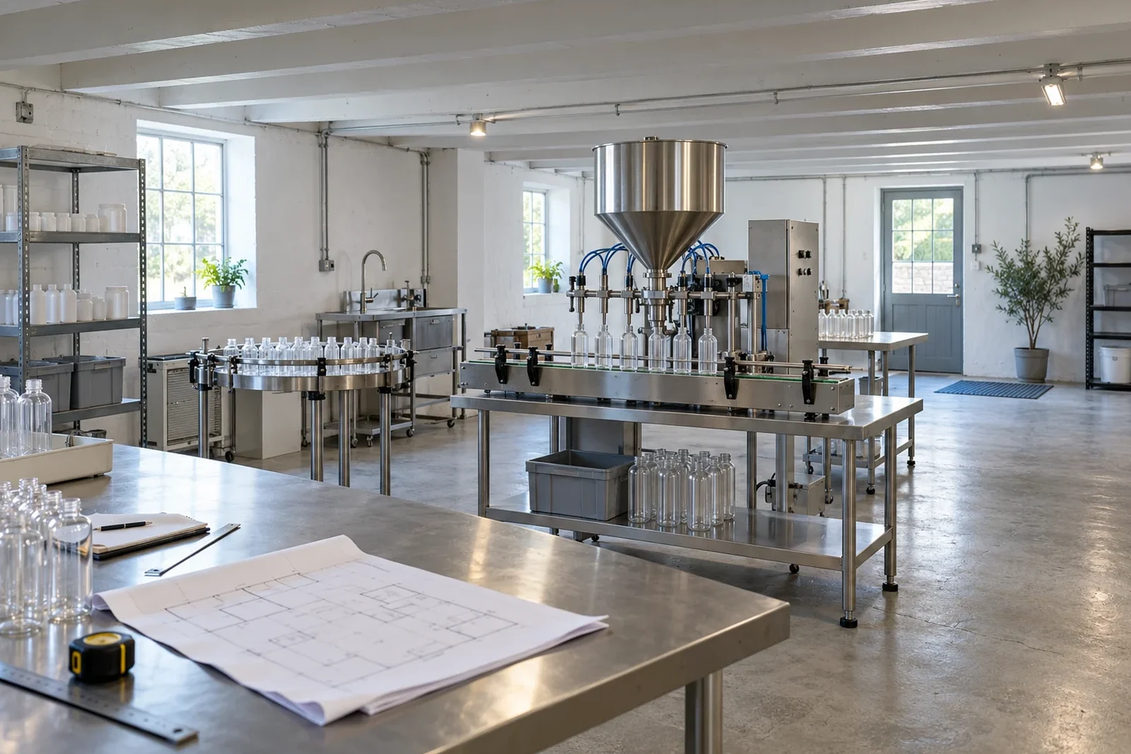
Designing a packaging line layout requires more than fitting individual machine frames inside a building column grid. When layout drawings place an unscrambler, filler, capper, labeler, cartoner, and case packer nose-to-tail at identical speeds with short transfer conveyors, routine reel splices and minor jams trigger cascading downtime stops across the entire line. At the same time, omitting door-swing envelopes, rear servicing space, and pallet staging lanes on the CAD drawing creates operator and maintenance bottlenecks as soon as production starts.
Structure your floor plan around three engineering layers: inter-station accumulation buffer capacity that isolates the core pacing machine from short stops, a V-curve speed profile paired with photo-eye and PLC state handshakes that drains accumulated queues without container damage, and code-verified floor clearances for electrical panels, exit routes, machine guarding, and forklift traffic. For the broader operational loop linking line layout to shift performance, return to our plant operations guides.
| Layout pillar | Engineering decision | Floor-plan parameters to lock before installation |
|---|---|---|
| Pacer isolation and buffer sizing | How many containers must accumulate between coupled stations during a splice or minor jam? | Core pacer speed, design stop survival window, repair-time distribution, live accumulation capacity, and buffer recovery time |
| Accumulation conveyor architecture | Which conveyor or table geometry fits the container stability, back-pressure limit, and floor footprint? | Medium-pressure belt, zero-pressure drop-roller, zero-contact roller, bi-directional mass-flow table, vertical spiral, or rotary turntable |
| V-curve speed balancing | How much catch-up speed do upstream and downstream stations need relative to the core pacer? | Baseline pacer rate, upstream prime speeds, downstream recovery speeds, and primary-to-secondary case packing surge margins |
| Sensor and state handshakes | How do conveyors and controllers modulate speed before a full blockage stops the pacer? | Queue photo-eye placement, drive slowdown timers, upstream feed stop timers, and blocked or starved boolean state tags |
| Electrical and egress clearances | Where do hinged cabinet doors, rear access panels, and pedestrian exit paths sit on the floor? | Front electrical working depth and width, hinged door swing arcs, rear deenergized access, headroom, and unobstructed exit route widths |
| Perimeter, changeover, and aisle access | Can operators stage film reels, changeover carts, and pallet trucks without blocking walkways? | Machine perimeter servicing offset, guard interlocking and energy isolation access, marked handling aisles, and unattended truck rules |
Why zero-buffer footprints and mismatched speeds stall coupled lines
A multi-machine packaging line operates as a coupled serial system where the slowest or most frequently interrupted station governs shift output. When stations are linked directly without intermediate surge space or capacity margins, any brief downstream hesitation forces upstream equipment into idle wait states. If you are auditing an already installed line to see where stops originate, combine the layout checks below with finding packaging line bottlenecks with basic production data and cartoner versus case packer selection.
Published line-integration studies and industry benchmark data highlight how unbuffered stops and undersized downstream stations constrain line output:
In AMD Machines’ buffer and accumulation conveyor design analysis, without buffering between stations on an automated production line, a 30-second jam at one station starves downstream stations and blocks upstream stations.
In E-PAK Machinery’s liquid filling line integration analysis, every station on a liquid filling line must handle at least the filler’s output rate: if a filler runs at 50 containers per minute but the downstream capper is rated for 35 containers per minute, the effective line speed is constrained to 35 containers per minute.
In Smartpack’s VFFS end-of-line layout analysis, required case packing speed equals VFFS bags per minute divided by bags per carton: a VFFS machine running at 120 bags per minute with a pack pattern of 24 bags per carton requires a minimum of 120 ÷ 24 = 5 cases per minute at the case erector, case packer, and case sealer, whereas a 4 cases per minute case packer forces the VFFS machine to stop.
According to PMMI’s 2026 Overall Equipment Effectiveness Quickie Survey Report (June 2, 2026, surveying 35 industry respondents), 45.7% of respondents offer an OEE tracking solution, 93.8% track downtime as a core OEE KPI, and 100.0% of $250 Million-plus respondents selected predictive maintenance metrics as an underserved capability.
Before locking conveyor lengths on a layout drawing, identify the primary pacing machine—typically the liquid filler, thermoformer, or vertical form-fill-seal bagger—and verify that every downstream station has both the cycle rate to outpace the pacer and the physical conveyor queue to absorb routine micro-stops.
Packaging line buffer sizing: MTTR baselines, N_buffer, and recovery time
Accurate packaging line buffer sizing converts expected micro-stop durations and station repair times into a physical container count and a required buffer drain window. Sizing a conveyor strictly by available floor gap rather than repair-time data and catch-up speed differential leaves the buffer unable to absorb routine label splices, carton magazine reloads, or brief sensor trips. For the full shift-level loss accounting behind these equations, see our packaging line OEE calculation and bottleneck analysis.
Automation integrators and packaging line models define the baseline repair-time rules and deterministic buffer equations as follows:
In AMD Machines’ buffer sizing guidance, a practical starting point for buffer sizing is the Mean Time To Repair (MTTR) of the less reliable adjacent station: a 3-minute average downtime event on a line running at 10 parts per minute requires a minimum buffer capacity of 30 parts.
As AMD Machines notes on repair-time variability, a buffer sized only for the average MTTR is insufficient roughly half the time; when line stoppage carries high costs, engineers size buffers for the 80th or 90th percentile repair time.
In the serial packaging line buffer model established in our packaging line OEE and bottleneck guide, required live empty buffer capacity equals N_buffer = v_core * t_stop, net buffer pull-down rate equals delta_v = v_downstream - v_core, and buffer recovery time equals t_recovery = N_buffer / (v_downstream - v_core) = (v_core * t_stop) / (v_downstream - v_core).
For a 120 packs/min (2.00 packs/s) core filler and a 120-second (2.0-minute) micro-stop survival window, the required live empty accumulation capacity is N_buffer = 2.00 packs/s * 120 s = 240 packs.
When a downstream labeler restarts at its V-curve catch-up rate of 138 packs/min while the core filler feeds at 120 packs/min, the net buffer pull-down rate is delta_v = 138 - 120 = 18 packs/min (0.30 packs/s).
Draining 240 accumulated packs at a net pull-down rate of 18 packs/min requires a buffer recovery time of t_recovery = 240 packs / 18 packs/min = 13.33 minutes (800 seconds).
At a 15% V-curve over-speed (v_downstream = 1.15 * v_core), draining a full accumulation buffer takes 1 / 0.15 = 6.67 times as long as the micro-stop that filled it (13.33 min / 2.0 min = 6.67).
Notice the layout implication of the recovery-time equation: if the downstream station stops again before the recovery window completes, the partially filled accumulation table reaches its high-level sensor early and blocks the core pacer. Pair physical buffer sizing with site-specific preventive maintenance checklists so the interval between recurring downstream stops exceeds the calculated drain time.
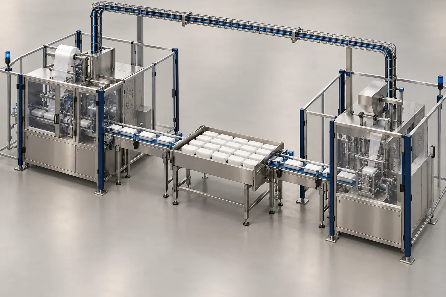
Selecting an accumulation conveyor: linear zones, mass-flow tables, vertical spirals, and rotary turntables
Once the required container count is known, translating that buffer capacity into floor dimensions depends on the accumulation conveyor mechanism, product fragility, and whether First-In-First-Out (FIFO) lot order must be preserved. When scoping complete line hardware, review choosing a packaging automation system alongside the equipment specifications below.
Peer OEM guides, trade journal case studies, and published equipment specifications document the primary conveyor classes, footprints, and rotary table configurations:
In Ideal Pase’s accumulation conveyor classification, packaging accumulation conveyors are categorized into three primary types: medium-pressure (flat drive belt over rollers), zero-pressure (pneumatic drop-roller zones), and zero-contact (motor-driven roller zones).
In Ideal Pase’s conveyor analysis, zero-contact accumulation conveyors use one or two motor-driven rollers (MDRs) joined by O-bands to non-powered rollers to stop individual single-item zones instantly without product contact or back pressure, though at a lower throughput rate than zero-pressure and medium-pressure conveyors.
In a Multi-Conveyor high-speed canning line layout modification reported by Packaging Strategies, the design paired a 51 ft mass flow transport conveyor section with a 54 ft long by 10 ft wide bi-directional accumulation table to hold nearly 14,000 cans at 900 cans per minute (CPM).
As reported by Packaging Strategies, the Garvey Vertical Infinity Accumulation Loop integrates two Ryson Mass Flow Spiral Conveyors with the Garvey Infinity Loop to use vertical space for zero-back-pressure accumulation and single-filing within a small floor footprint.
According to SIGMA Equipment specifications, the ITW Hartness DYNAC Model 6900 is a high-speed single-file FIFO (First In First Out) zero-pressure helical accumulation and buffering conveyor that dynamically responds to line conditions with pressure-less product handling.
According to SIGMA Equipment specifications, the ITW Hartness DYNAC 6400 vertical accumulation conveyor provides 278 linear feet of vertical accumulation with an 11.06-inch (11-inch) vertical product clearance height, plastic tabletop chain, stainless steel construction, and plexiglass guarding.
According to Kinex Cappers product specifications, Kinex Cappers Open Frame and Enclosed Frame rotary accumulation tables feature a 35 to 39 inch adjustable floor-to-disk height, 0 to 5 inch adjustable guide rail height, 1/8 inch (11 Gauge) disk thickness, 0 to 8 RPM variable speed, 300 lb maximum weight capacity, and 115 V, 60 Hz, single-phase power.
In Kinex Cappers published pricing, Kinex Cappers Open Frame rotary accumulation tables are offered in 24, 36, 48, and 60 inch disk diameters, priced at $3,905 (24 in.), $4,290 (36 in.), $4,730 (48 in.), and $5,720 (60 in.) for the standard table, up to $7,535 for a 60-inch table with unscrambler and in-feed table.
In Kinex Cappers published pricing, Kinex Cappers Enclosed Frame rotary accumulation tables are priced at $4,125 (24 in.), $4,620 (36 in.), $5,060 (48 in.), and $6,270 (60 in.) for the standard configuration, and up to $8,085 for the 60-inch model with unscrambler and in-feed table.
According to Jerry Packaging specifications, the Jerry Packaging JSP-900 / JGP-900 accumulating rotary turntable is built with a heavy-duty 304SS frame, 900 mm standard top diameter, 900 mm ± 50 mm standard height, tool-less single side rail adjustments, and a 220 V, single-phase, 4 A, 50-60 Hz power supply.
Use the comparison matrix below to match the accumulation hardware class to your container format and plant floor constraints:
| Accumulation hardware class | Container handling mechanism | Floor layout role |
|---|---|---|
| Medium-pressure flat drive belt over rollers | Continuous flat belt drives rollers beneath queued packages | Straight conveyor runs handling rigid secondary cartons and cases |
| Zero-pressure pneumatic drop-roller zones | Pneumatic actuator drops drive rollers below the carrying plane when a zone fills | Inline zone buffering where back-pressure reduction is required across straight lanes |
| Zero-contact motor-driven roller zones | Motor-driven rollers linked by O-bands stop individual item zones without contact | Fragile or irregular packs requiring zero back pressure and discrete item separation |
| Bi-directional mass-flow accumulation table | Wide multi-lane table reverses or sweeps product into a dense mass-flow bank | High-volume cylindrical container buffering where horizontal floor width is available |
| Vertical spiral or helical accumulator | Elevated spiral or variable-path helical track stores single-file or mass-flow packs vertically | Tight floor footprints where overhead height can replace long horizontal tables |
| Rotary accumulation turntable | Rotating stainless disk circulates upright round containers inside adjustable guide rails | Compact infeed unscrambling, mid-line buffering, or end-of-line pack collection |
V-curve line speed balance and end-of-line surge margins
Physical accumulation conveyors cannot drain unless downstream stations run faster than the core pacing machine during recovery. A v curve line speed balance sets the critical pacing machine as the speed trough of the line and steps up the target recovery rates of both upstream and downstream equipment as distance from the pacer increases.
Line-integration guides and reference V-curve profiles establish the station-by-station speed multipliers and VFFS-to-case-packer capacity tiers:
In Foodmach’s V-Curve line speed balancing methodology, the slowest critical machine sets the baseline speed, the two neighboring machines immediately before and after the critical machine run 10% faster during recovery phases, and machines further along the line run incrementally faster—typically by 10%.
In Fill Package’s conveyor speed chain design guide, downstream capacity is generally set 10-15% higher than upstream supply to create a gap and prevent blockage, paired with calculated accumulation buffer time such as 2 minutes of buffer for film or label changes.
On a 120 packs/min (2.00 packs/s) reference V-curve line, the Upstream 2 bulk unscrambler or depalletizer is tuned to 125% to 130% of v_core (150 to 156 packs/min), running at nominal 105% when the infeed queue is full and ramping to 125%+ after a bulk bin reload.
On a 120 packs/min reference V-curve line, the Upstream 1 bottle rinser or air cleaner is tuned to 110% to 115% of v_core (132 to 138 packs/min) to maintain a flooded prime queue at the filler infeed worm.
On a 120 packs/min reference V-curve line, Downstream 1 stations (capper, labeler, checkweigher) are rated at 110% to 115% of v_core (132 to 138 packs/min, or 2.20 to 2.30 packs/s), running at 100% (120 PPM) when the upstream buffer is empty and ramping to 115% (138 PPM) when the buffer passes medium level.
On a 120 packs/min reference V-curve line, the Downstream 2 secondary cartoner or case packer is tuned to 115% to 120% of v_core (138 to 144 packs/min, or 2.30 to 2.40 packs/s) to absorb carton-magazine blank loading pauses and drain the primary-to-secondary accumulation table.
On a 120 packs/min reference V-curve line, the Downstream 3 palletizer and stretch wrapper are tuned to 125% to 130% of v_core (150 to 156 packs/min equivalent) to clear case conveyor queues after full-pallet discharge and slip-sheet insertion cycles.
In Smartpack’s VFFS end-of-line layout framework, recommended VFFS end-of-line layout tiers by bagger output are: 30–60 bags/min (discharge conveyor + inspection + manual packing table), 60–100 bags/min (semi-auto system or automatic case sealing), 100–160 bags/min (automatic case packing system), and 160+ bags/min (automatic case packing + robotic palletizing).
To absorb rejects, short stops, unstable spacing, changeover, and palletizing demand, Smartpack specifies case packer capacity above theoretical case speed: 7–8 cases/min for 6 cases/min theoretical (60 bags/min at 10 bags/case), 9–10 cases/min for 8 cases/min (80 bags/min at 10 bags/case), around 10 cases/min for 8.3 cases/min (100 bags/min at 12 bags/case), and around 12 cases/min for 10 cases/min (120 bags/min at 12 bags/case).
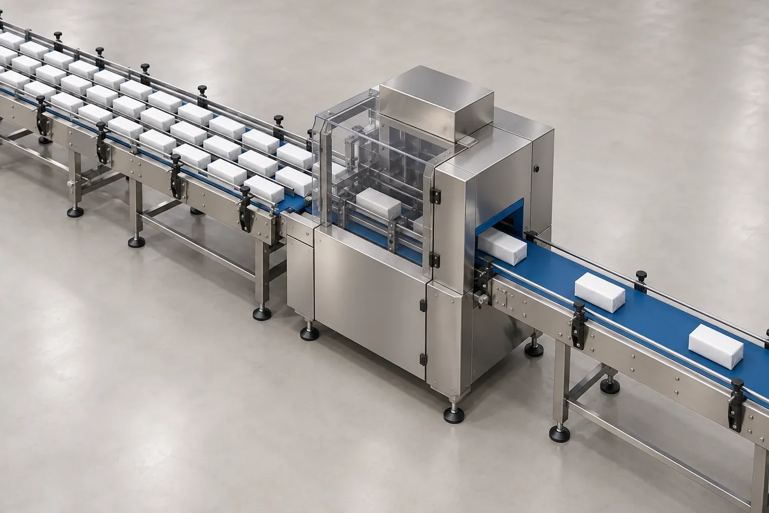
Conveyor photo-eye modulation, PackML state handshakes, and changeover access
A V-curve speed profile requires automated sensor feedback and standardized machine-to-machine state handshakes so downstream equipment ramps smoothly rather than oscillating between hard stops and full speed. Specify these electrical and control signals before ordering equipment using the packaging line integration checklist, and design physical staging space around each machine for the packaging format changeover checklist.
Conveyor engineering guides, control standards, PLC library documentation, and quick-changeover benchmarks define the handshake and changeover parameters:
In Fill Package’s conveyor control guidance, automated photo-eye backup control logic on a packaging conveyor slows the VFD to 50% speed if a sensor detects product backup for 3 seconds, and stops the upstream feed if the backup persists for 10 seconds.
PackML was adopted by ISA as ISA-TR88.00.02-2022 (Machine and Unit States: An implementation example of ISA-88.00.01), a technical report giving an example implementation of machine/unit state models, modes, and tag naming.
In the Beckhoff TwinCAT 3 Tc3_PackML_V3 PLC library (version 1.0.3, from TwinCAT 3.1 Build 4024.63), the ST_PMLEquipment structure defines two boolean tags—Blocked : BOOL and Starved : BOOL—for signaling downstream blockage or upstream starvation of a packaging machine.
The Beckhoff TwinCAT 3 Tc3_PackML function block PS_PackML_StateMachine_Auto (from TwinCAT v3.1 build 4018 onwards) implements the PackML Machine State Model V3 boolean state outputs, including ST_Execute, ST_Complete, ST_Idle, ST_Held, ST_Suspended, ST_Stopped, and ST_Aborted.
In Wolf Packing’s multi-size bagging changeover analysis, traditional bagging format changeovers require 30 to 90 minutes, whereas quick-changeover systems with tool-less mechanisms, modular sealing jaws (removable in 3 minutes), servo-driven formers (for 2 to 16 inch bag widths), and touchscreen HMI storage (for 50 to 200-plus SKU recipes) cut changeover time by 70 to 85% down to 5 to 15 minutes (or from 90 minutes to 9 minutes, an 88% reduction, using SMED).
On the floor plan, mark the exact mounting positions for low-level (prime), medium-level (V-curve ramp), and high-level (backup slowdown and upstream hold) photo-eyes along each inter-station conveyor, and reserve space beside the bagger or cartoner for staging modular change parts and pre-inspected film reels while the line is running.
Operator, electrical panel, exit route, perimeter, and forklift floor clearances
Even a mathematically balanced V-curve layout fails plant safety and maintenance audits if conveyors or auxiliary frames encroach on electrical working spaces, emergency exit routes, machine service perimeters, or forklift aisles. Verify every floor-plan dimension against the regulatory and machinery safety requirements below before anchoring frames to the slab.
Electrical control panel and MCC working space
Federal electrical rules and industrial machinery electrical standards specify the working space depths, widths, door-swing angles, rear access, headroom, and overhead zones around control enclosures:
Under OSHA standard 1910.303(g)(1)(i)(B) and 1910.303(g)(1)(i)(C) for electrical equipment operating at 600 volts, nominal, or less to ground, the width of working space in front of the equipment shall be the width of the equipment or 762 mm (30 in.), whichever is greater, must permit at least a 90-degree opening of equipment doors or hinged panels, and associated equipment above or below may extend not more than 153 mm (6 in.) beyond the front.
Under OSHA standard 1910.303 Table S-1 (Minimum Depth of Clear Working Space at Electric Equipment, 600 V or Less), the minimum clear depth is 0.9 m (3.0 ft) for 0–150 V across Conditions A, B, and C, and for 151–600 V is 0.9 m (3.0 ft) under Condition A, 1.0 m (3.5 ft) under Condition B (exposed live parts on one side and grounded parts on the other), and 1.2 m (4.0 ft) under Condition C (exposed live parts on both sides).
Under OSHA standard 1910.303 Table S-1 Note 3, where rear access is required to work on deenergized parts on the back of enclosed electrical equipment, a minimum horizontal working space of 762 mm (30 in.) shall be provided.
Under OSHA standard 1910.303(g)(1)(iv), electrical equipment rated 1200 amperes or more and over 1.83 m (6.0 ft) wide requires one entrance not less than 610 mm (24 in.) wide and 1.98 m (6.5 ft) high at each end of the working space, unless unobstructed exit travel or doubled working space is provided.
Under OSHA standard 1910.303(g)(1)(vi)(A) and 1910.303(g)(1)(vi)(B), the minimum headroom of working spaces about service equipment, switchboards, panelboards, or motor control centers is 1.91 m (6.25 ft) for installations built before August 13, 2007, and 1.98 m (6.5 ft) (or the height of the equipment if it exceeds 1.98 m / 6.5 ft) for installations built on or after August 13, 2007.
Under OSHA standard 1910.303(g)(1)(vii)(A)(1), indoor switchboards, panelboards, distribution boards, and motor control centers require a dedicated space equal to the width and depth of the equipment extending from the floor to a height of 1.83 m (6.0 ft) above the equipment or to the structural ceiling, whichever is lower, kept free of foreign piping, ducts, or equipment.
IEC 60204-1:2016+AMD1:2021 CSV (Safety of machinery — Electrical equipment of machines — Part 1: General requirements) and NFPA 79 (Electrical Standard for Industrial Machinery, 2024 Edition) govern electrical, electronic, and programmable electronic equipment of industrial machinery operating at up to 1000 V ac / 1500 V dc.
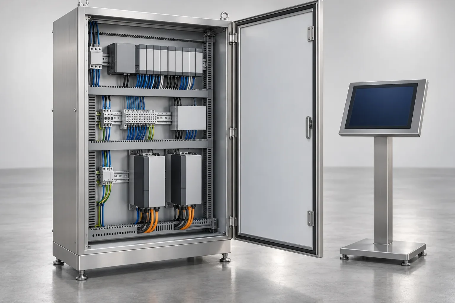
Exit routes, walking-working surfaces, and machine perimeter access
Workplace exit route regulations, walking-working surface rules, and OEM footprint specifications govern pedestrian walkways and all-sides machine access:
Under OSHA standard 1910.36(g)(1) and 1910.36(g)(2) (Exit Routes), the ceiling of an exit route must be at least 7 feet 6 inches (2.3 m) high with no projection reaching less than 6 feet 8 inches (2.0 m) from the floor, and an exit access must be at least 28 inches (71.1 cm) wide at all points.
Under OSHA standard 1910.36(e)(2) and 1910.36(h)(4), a side-hinged door connecting any room to an exit route must swing out in the direction of exit travel if the room is designed to be occupied by more than 50 people or is a high hazard area, and an outdoor exit route must not have a dead-end longer than 20 feet (6.2 m).
Under OSHA standard 1910.37(a)(3), 1910.37(b)(6), and 1910.37(b)(7), exit routes must remain free and unobstructed with no materials or equipment placed permanently or temporarily within the exit route, exit signs must be illuminated to a surface value of at least 5 foot-candles (54 lux), and the word ‘Exit’ must use letters not less than 6 inches (15.2 cm) high with principal strokes not less than three-fourths of an inch (1.9 cm) wide.
Under OSHA standard 1910.22(a)(1), 1910.22(a)(2), and 1910.22(c) (Walking-Working Surfaces), passageways and walking-working surfaces must be kept clean, orderly, and sanitary, wet-process floors must maintain drainage and provide dry standing places such as false floors, platforms, and mats, and safe means of access and egress must be provided.
As an OEM machine footprint benchmark, the CECLE HSP-200 automatic straw filling and sealing machine frame measures 82 cm width by 78 cm depth by 151 cm height (or 95 cm length with the integrated smart counting belt), weighs approximately 220 kg, fits in rooms as narrow as 1.2 meters wide, and requires at least 30 cm clearance on all sides for maintenance access, cooling airflow, and operator safety.
Forklift aisles, machine guarding, LOTO, and packaging safety standards
Material-handling aisle rules, powered industrial truck regulations, machine guarding and energy-isolation rules, and international packaging machinery safety standards govern how mobile equipment and technicians interact around the line:
Under OSHA standard 1910.176(a) and 1910.176(e) (1910 Subpart N, Materials Handling and Storage), where mechanical handling equipment is used, sufficient safe clearances shall be allowed for aisles, at loading docks, through doorways, and wherever turns or passage must be made; permanent aisles and passageways shall be appropriately marked and kept clear of obstructions, and clearance signs to warn of clearance limits shall be provided.
Under OSHA standard 1910.178(m)(5)(i) and 1910.178(m)(5)(ii), a powered industrial truck (forklift) is considered unattended when the operator is 25 ft. or more away from the vehicle in view (or whenever out of view), requiring load-engaging means fully lowered, controls neutralized, power shut off, and brakes set.
Under OSHA standard 1910.178(n)(1), 1910.178(n)(4), 1910.178(n)(5), and 1910.178(n)(7)(i), powered industrial trucks must maintain approximately three truck lengths from the truck ahead, slow down and sound the horn at cross aisles and obstructed-vision locations, travel with the load trailing when forward view is obstructed, never park closer than 8 feet from the center of railroad tracks, and drive with the load upgrade on grades in excess of 10 percent.
Under OSHA standard 1910.212(a)(1), 1910.212(a)(5), and 1910.212(b) (Machinery and Machine Guarding), machine guarding (such as barrier guards, two-hand tripping devices, or electronic safety devices) shall protect operators and employees from point of operation, ingoing nip points, and rotating parts; fan blades less than 7 feet above the floor shall be guarded with openings no larger than 1/2 inch; and fixed machinery shall be securely anchored to prevent walking or moving.
Under OSHA standard 1910.147(a)(2)(ii)(A) and 1910.147(a)(2)(ii)(B) (The Control of Hazardous Energy — Lockout/Tagout), servicing or maintenance taking place during normal production operations is covered by lockout/tagout whenever an employee is required to remove or bypass a guard or safety device, or place any part of his or her body into a point of operation or associated danger zone.
ANSI/PMMI B155.1-2023 (American National Standard on the Safety of Packaging and Processing Machinery, released August 31, 2023, with clauses 4 and 5 reorganized) guides machinery suppliers, users, modifiers, and co-packers through a formal, documented risk assessment process and includes whole-body access requirements, updated legacy machinery responsibilities, and guidelines for mobile platforms and logistics robots.
ISO 12100:2010 (Safety of machinery — General principles for design — Risk assessment and risk reduction) sets out basic terminology, principles, and a methodology for risk assessment and risk reduction in the design of machinery, while ISO 13850:2015 specifies functional requirements and design principles for the emergency stop function and ISO 14119:2024 sets out principles for guard interlocking devices.
EN 415-10:2014 (Safety of packaging machines — Part 10: General requirements) sets out general safety requirements for packaging machines in the EU to be used with machine-specific parts such as EN 415-3:2021 (Part 3: Form, fill and seal machines; fill and seal machines), while ISO 22400-2:2014 defines manufacturing operations management KPIs and 29 CFR 1910.147 sets minimum performance requirements for lockout/tagout.
Copy-ready packaging line layout verification checklist
Use the verification table below during layout design reviews to confirm that accumulation capacity, V-curve speed gradients, sensor handshakes, and floor clearances are documented on the plant CAD drawing before equipment installation begins.
| Layout zone | Verification item | Floor-plan check to record | Operational consequence if omitted |
|---|---|---|---|
| Core pacing station | Baseline cycle rate and downstream capacity check | Verify that every downstream station exceeds the pacer cycle rate | A slower downstream station becomes the permanent line constraint |
| Inter-station buffers | Live container capacity and drain window | Record target stop survival time, live pack capacity, and recovery time | Short splices or jams immediately block the upstream filler or bagger |
| Accumulation hardware | Conveyor class and container stability match | Select belt, drop-roller, roller-zone, mass-flow table, spiral, or rotary table | Excess back pressure tips unstable containers or scuffs printed labels |
| V-curve speed chain | Upstream prime and downstream catch-up speeds | Document nominal and recovery speed settings for each station around the pacer | Accumulated queues never drain between consecutive micro-stops |
| End-of-line case packing | Pack pattern and case surge margin | Confirm case packer speed includes surge margin above theoretical bag output | Bag discharge backs up whenever the case erector or packer hesitates |
| Conveyor sensor logic | Photo-eye slowdown and feed-stop timers | Mark low, medium, and high queue sensors and drive slowdown logic on drawings | Abrupt hard stops topple containers and cause transfer-plate jams |
| PLC state handshakes | Standardized blocked and starved tags | Map upstream starvation and downstream blockage boolean signals across controllers | Downtime logs blame the pacer for stops caused by adjacent stations |
| Electrical enclosures | Front working depth, width, headroom, and door swing | Draw full cabinet door-swing arcs and dedicated overhead space on the layout | Conveyors or piping block panel doors and violate electrical working space rules |
| Pedestrian exit access | Unobstructed walkway width and overhead projection height | Keep permanent and temporary staging out of exit routes and verify sign visibility | Pallet staging or low conveyor crossovers obstruct emergency egress |
| Material handling and servicing | Marked forklift aisles, perimeter access, and energy isolation | Mark permanent handling aisles, machine anchoring, guard interlocks, and lockout points | Forklift turns, film roll loading, and maintenance carts interfere with running lines |
FAQ
How do you calculate required accumulation buffer capacity and recovery time between two packaging machines?
In the serial packaging line buffer model established in our packaging line OEE and bottleneck guide, required live empty buffer capacity equals N_buffer = v_core * t_stop, net buffer pull-down rate equals delta_v = v_downstream - v_core, and buffer recovery time equals t_recovery = N_buffer / (v_downstream - v_core) = (v_core * t_stop) / (v_downstream - v_core). For a 120 packs/min (2.00 packs/s) core filler and a 120-second (2.0-minute) micro-stop survival window, the required live empty accumulation capacity is N_buffer = 2.00 packs/s * 120 s = 240 packs, and draining 240 accumulated packs at a net pull-down rate of 18 packs/min requires a buffer recovery time of t_recovery = 240 packs / 18 packs/min = 13.33 minutes (800 seconds).
What is the difference between medium-pressure, zero-pressure, and zero-contact accumulation conveyors?
In Ideal Pase’s accumulation conveyor classification, packaging accumulation conveyors are categorized into three primary types: medium-pressure (flat drive belt over rollers), zero-pressure (pneumatic drop-roller zones), and zero-contact (motor-driven roller zones). Zero-contact accumulation conveyors use one or two motor-driven rollers (MDRs) joined by O-bands to non-powered rollers to stop individual single-item zones instantly without product contact or back pressure, though at a lower throughput rate than zero-pressure and medium-pressure conveyors.
How much faster should upstream and downstream stations run on a V-curve packaging line layout?
In Foodmach’s V-Curve line speed balancing methodology, the slowest critical machine sets the baseline speed, the two neighboring machines immediately before and after the critical machine run 10% faster during recovery phases, and machines further along the line run incrementally faster—typically by 10%. On a 120 packs/min reference V-curve line, Downstream 1 stations (capper, labeler, checkweigher) are rated at 110% to 115% of v_core (132 to 138 packs/min, or 2.20 to 2.30 packs/s), the Downstream 2 secondary cartoner or case packer is tuned to 115% to 120% of v_core (138 to 144 packs/min, or 2.30 to 2.40 packs/s), and the Downstream 3 palletizer and stretch wrapper are tuned to 125% to 130% of v_core (150 to 156 packs/min equivalent).
What floor clearance is required in front of packaging line electrical panels operating at 600 volts or less?
Under OSHA standard 1910.303(g)(1)(i)(B) and 1910.303(g)(1)(i)(C) for electrical equipment operating at 600 volts, nominal, or less to ground, the width of working space in front of the equipment shall be the width of the equipment or 762 mm (30 in.), whichever is greater, must permit at least a 90-degree opening of equipment doors or hinged panels, and associated equipment above or below may extend not more than 153 mm (6 in.) beyond the front. Under OSHA standard 1910.303 Table S-1 (Minimum Depth of Clear Working Space at Electric Equipment, 600 V or Less), the minimum clear depth is 0.9 m (3.0 ft) for 0–150 V across Conditions A, B, and C, and for 151–600 V is 0.9 m (3.0 ft) under Condition A, 1.0 m (3.5 ft) under Condition B (exposed live parts on one side and grounded parts on the other), and 1.2 m (4.0 ft) under Condition C (exposed live parts on both sides).
Sources
- AMD Machines — Buffer and Accumulation Conveyor Design (June 30, 2025)
- RE Digital Editions — Packaging Line OEE Calculation and Bottleneck Analysis
- Packaging Strategies — Bi-Directional Accumulation for Super High-Speed Filling (July 7, 2020)
- Packaging Strategies — Garvey Introduces Infinity Accumulation Loop with Ryson Spiral Conveyor (October 6, 2017)
- SIGMA Equipment — ITW Hartness DYNAC 6900 & 6400 Vertical Accumulation Conveyors Specifications
- Ideal Pase — Choosing the Right Accumulation Solution (May 14, 2026)
- Kinex Cappers — Open Frame and Enclosed Frame Rotary Accumulation Tables Specifications & Pricing
- Jerry Packaging — JSP-900 / JGP-900 Accumulating Rotary Turntable Specifications
- Foodmach — V-Curve Theory and OEE: How V-Curve Theory Helps OEE
- Fill Package — How to Design an Efficient Conveyor System for Packaging Lines: An Engineering Guide (January 21, 2026)
- E-PAK Machinery — Filling Line Integration: How Fillers, Cappers, Conveyors, & Labelers Work Together (July 23, 2026)
- Smartpack — What is a Typical End-of-Line Layout for a VFFS Packaging Line? (June 8, 2026)
- Smartpack — Snack Packaging Line Layout: From VFFS Bagging to Case Packing and Robotic Palletizing (June 21, 2026)
- ISA-TR88.00.02-2022 — Machine and Unit States: An Implementation Example of ISA-88.00.01 (PackML)
- Beckhoff Automation Infosys — ST_PMLEquipment (TwinCAT 3 PLC Library: Tc3_PackML_V3)
- Beckhoff Automation Infosys — PS_PackML_StateMachine_Auto (TwinCAT 3 PLC Library: Tc3_PackML)
- PMMI — 2026 Overall Equipment Effectiveness Quickie Survey Report (June 2, 2026)
- Wolf Packing — Multi-Size Bagging: Quick Changeover Systems for Diverse SKUs (June 17, 2026)
- OSHA 29 CFR 1910.176 — Handling Materials - General (Aisles, Passageways, and Mechanical Equipment Clearances)
- OSHA 29 CFR 1910.178 — Powered Industrial Trucks (Forklift Operation and Aisle Travel Rules)
- OSHA 29 CFR 1910.303 — General Electrical Requirements (1910.303(g) Working Space and Table S-1 Clearances)
- OSHA 29 CFR 1910.36 — Design and Construction Requirements for Exit Routes
- OSHA 29 CFR 1910.37 — Maintenance, Safeguards, and Operational Features for Exit Routes
- OSHA 29 CFR 1910.22 — Walking-Working Surfaces: General Requirements
- OSHA 29 CFR 1910.212 — General Requirements for All Machines (Machine Guarding and Anchoring)
- OSHA 29 CFR 1910.147 — The Control of Hazardous Energy (Lockout/Tagout)
- CECLE Machine — HSP-200 Packaging Machine Footprint and Perimeter Clearance Specification
- PMMI — ANSI/PMMI B155.1-2023 Safety Requirements for Packaging and Processing Machinery Release
- RE Digital Editions — Verified Standards Reference Registry
Update history
- : First published.
Next steps
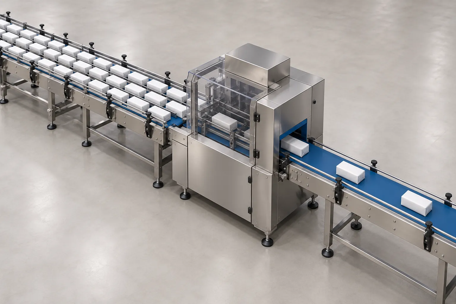
Finding Packaging Line Bottlenecks with Basic Production Data
Identify candidate packaging-line constraints using four analysis groups, measured good-pack counts and running rates, with a worked example and copyable shift log.
Read guide Packaging Line OEE Calculation and Bottleneck Analysis: PackML States, V-Curve Speeds and SMED
Run a packaging line OEE calculation that separates Availability, Performance and Quality, maps PackML Starved and Blocked timers, and sizes V-curve buffers.
Read guide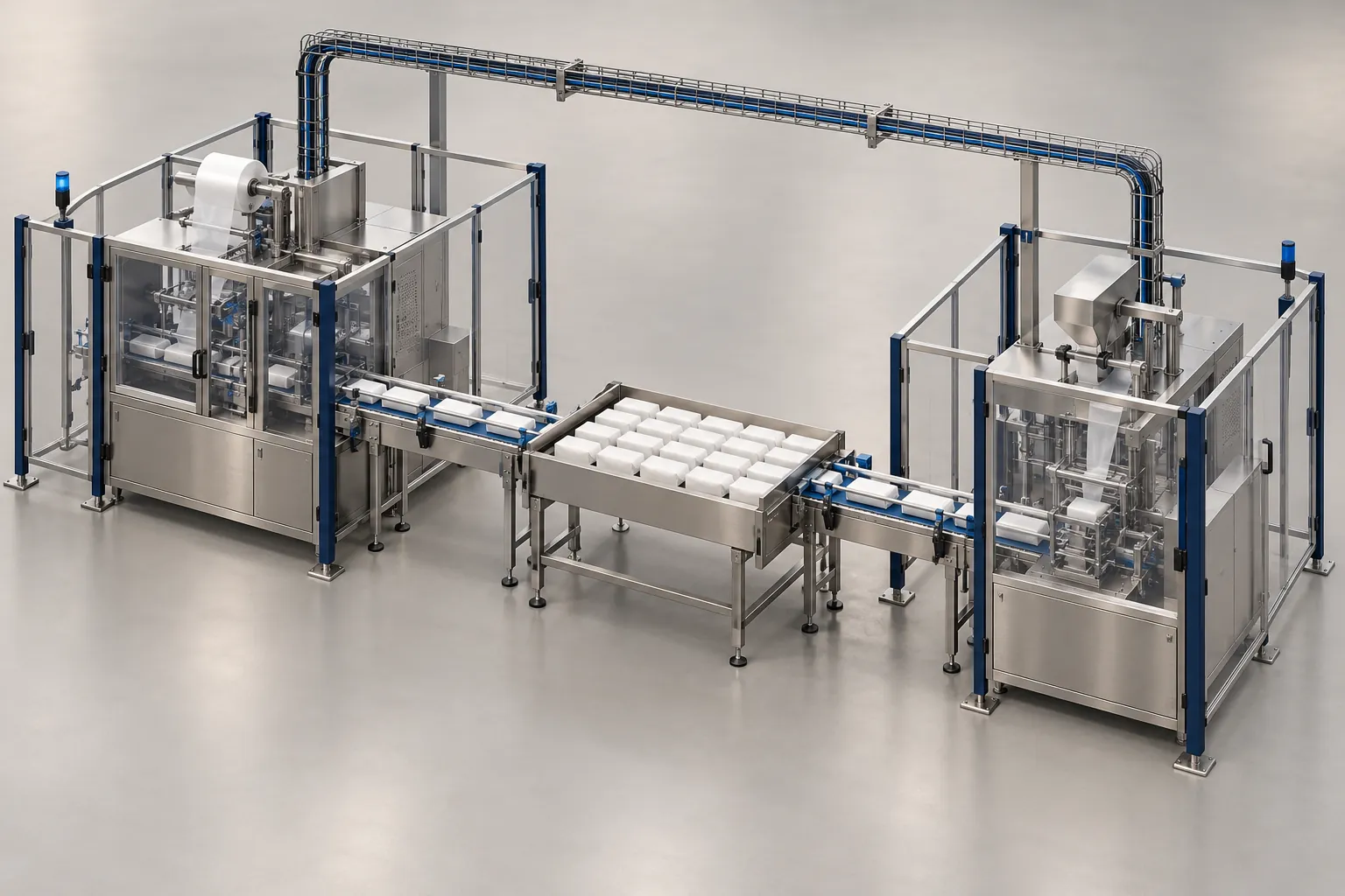
Packaging Line Integration Checklist: Interfaces to Confirm Before Ordering
Checklist of mechanical, electrical, signal, communication, safety and utility interfaces to settle before ordering a machine for a packaging line.
Read guide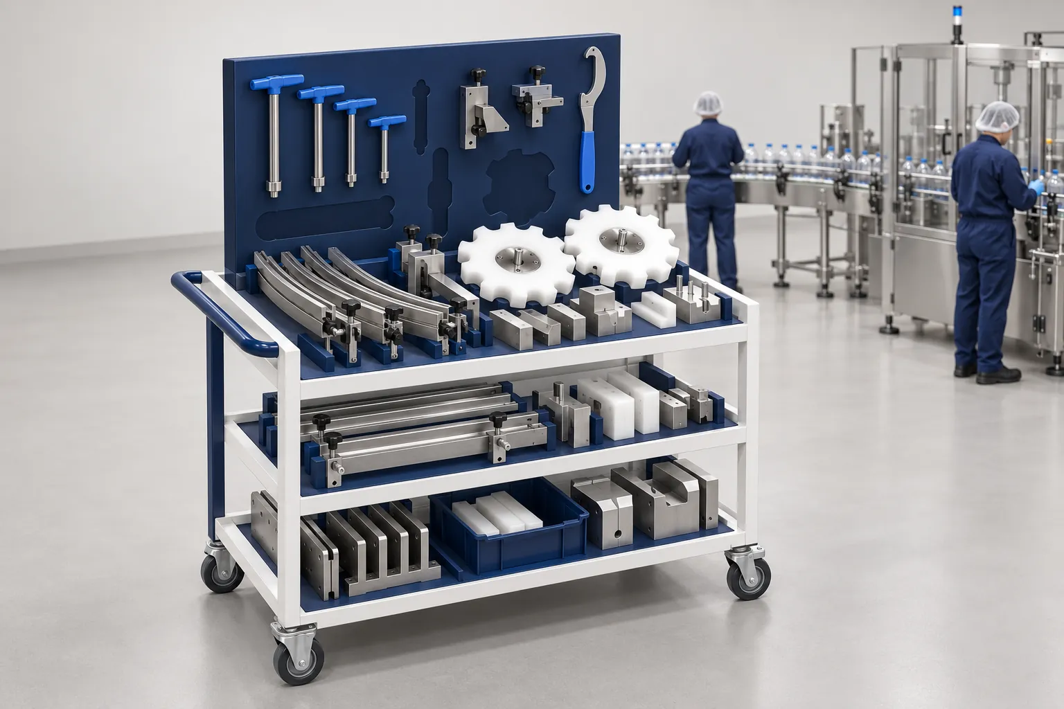
Packaging Format Changeovers: What to Record and Verify
A format changeover checklist: seven steps from preparation to run monitoring, a record template, and the SMED idea of external versus internal work.
Read guide