
Multihead Weigher Combination Scale Setup: Selection, Surfaces and Timing
Set up a multihead weigher combination scale by checking hopper selection, sticky-product contact parts and the discharge handshake with the bagger.
For multihead weigher combination scale setup, establish stable partial weights, select an acceptable combination near the target, and confirm that the selected product reaches the intended bag within its receiving window. Match contact parts to sticky-product behaviour and verify the bagger handshake, including stops and restart, before increasing output.
Applies to: Setup planning and trial records for combination weighers feeding a bagger. Uses a public Ohlson manual as a documented mechanism example; signal settings, calibration, contact parts and acceptance limits must match the installed equipment and product.

A correct combination on the screen can still produce a short bag if product stays in a hopper or arrives late. Multihead weigher combination scale setup therefore has to connect hopper selection, product release and the bagger’s receiving window.
Set up the combination scale in the order that product moves: establish repeatable partial hopper loads, verify selection against the agreed target and limits, check complete discharge through the contact path, and prove coordination with the bagger. Increase production demand only after those checks hold together. This guide assumes the multihead route has already been chosen; use auger fillers versus multihead weighers for the earlier dosing-system decision.
Start with the installed heads and the product recipe
Head count describes the available weighing positions, not the number that must discharge into every bag. Record the installed model and which heads are actually enabled before evaluating combinations.
The public Ohlson MHW10/MHW14 manual, reviewed October 19, 2026, lists 10 weigh buckets for MHW-CW10 and 14 weigh buckets for MHW-CW14 in its main-parameters table, printed pages 4–5. Those counts belong to the models described by that manual; they are not a definition of every multihead weigher.
Begin the setup record with the product state, target portion, acceptance basis, available hopper set, recipe revision and downstream pack format. Include the product at its expected temperature and after the expected holding time. An immediate trial on freshly prepared material may miss the handling condition that appears after a production stop.
Before collecting dose results, verify that contact parts are installed correctly, the machine is clear and the weighing system passes its prescribed checks. Follow the installed manual for zeroing and calibration. Do not use a recipe adjustment to compensate for a mechanical contact, an incorrectly seated hopper or a drifting empty indication.
Select a combination from ready hopper weights
A combination scale chooses a subset of measured partial loads. In the Ohlson manual’s theory-of-operation section, feed buckets replenish weigh buckets, and the computer compares stored weights to select a combination closest to the target. The recipe’s permitted range and exceptional-discharge behaviour also matter.
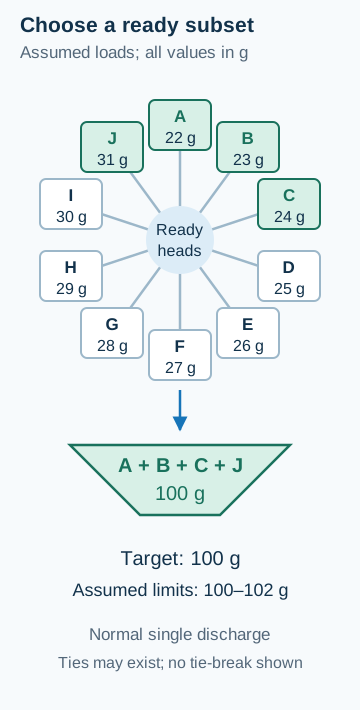
Assumed ready-hopper snapshot for the worked example below. Highlighting shows one exact-target subset, not an OEM tie-breaking rule.
For a normal discharge, an editorial mathematical description of that method is:
W(S) = Σ wᵢ for i in S; choose an allowed subset S minimizing |W(S) − T|, subject to L ≤ W(S) ≤ U.
wᵢ is the measured product mass in a ready hopper, S is the selected set of hoppers, T is target mass, and L and U are the permitted lower and upper masses, all in grams. Only stable, available hopper readings belong in this simplified candidate set. Installed controllers can impose additional conditions; the expression does not reproduce proprietary firmware.
Worked target-weight example
Teaching assumptions, prepared October 19, 2026: all 10 hoppers are ready; hopper loads A–J are respectively 22 g, 23 g, 24 g, 25 g, 26 g, 27 g, 28 g, 29 g, 30 g and 31 g. The target is 100 g and the assumed permitted range is 100–102 g. Normal single-discharge operation applies, with no forced discharge or multi-dump. These numbers illustrate the manual’s selection method; they are not accuracy results, recommended limits or legal net-content requirements.
Swipe sideways to see the other columns. The first column stays visible.
| Candidate subset | Arithmetic using the assumed loads | Selection result |
|---|---|---|
| A + B + C + I | 22 g + 23 g + 24 g + 30 g = 99 g | Below the assumed 100 g lower limit |
| A + B + C + J | 22 g + 23 g + 24 g + 31 g = 100 g | Exact target; an optimal permitted combination |
| A + B + D + J | 22 g + 23 g + 25 g + 31 g = 101 g | Permitted, but farther from target than the exact subset |
The worked result is W({A,B,C,J}) = 100 g, with a target difference of 100 g − 100 g = 0 g. Another subset may tie; the manual does not establish the tie-break used in this example. After discharge, the selected heads need to refill and settle before they can contribute again. Recalculate from the next ready snapshot rather than treating the illustrated set as a repeating recipe.
If no permitted combination is available, inspect feed balance, available heads and exceptional-discharge settings before widening the limits. The manual describes forced-combination functions. Record how the installed system identifies and handles an out-of-range discharge; a controller that keeps cycling has not necessarily maintained the agreed acceptance range.
Match sticky-product contact parts to the complete path
For sticky product, judge the contact path by repeatable delivery and cleanability, not by an isolated hopper reading. Product held on a pan, gate or chute can change the next dose even when combination arithmetic is correct.
Ishida’s Screwfeeder weigher description describes rotating screws and specialist contact parts for sticky protein applications. Its multihead range brochure also lists stainless-steel, embossed and shutter-surface options across the ranges shown. These are configuration choices to assess with the supplier; they do not mean that a standard vibratory machine becomes suitable for sticky product through a software setting.
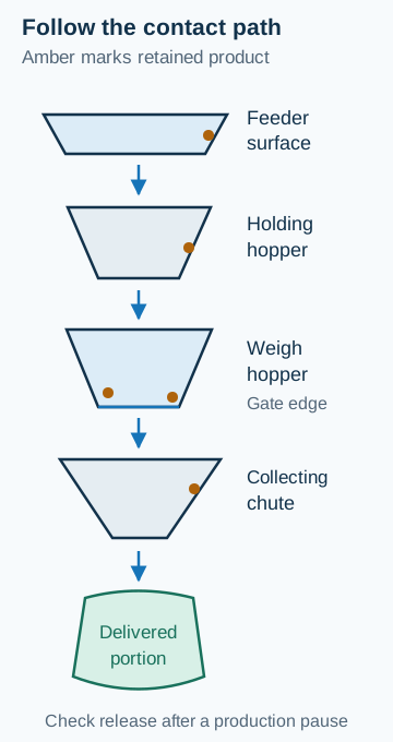
Inspect where product remains as well as where it is weighed. Gate corners and the final chute belong in the contact-part trial. Schematic.
Make a contact-part inventory covering the dispersion area, feeders, holding hoppers, weigh hoppers, gates, collecting surfaces and final delivery chute. For each supplied surface, record its identity, product-contact documentation, removal method and cleaning restrictions. Do not specify an aftermarket coating simply as “non-stick” without identifying its suitability for the product and cleaning process.
During the trial, observe residue after normal discharge and after the longest intended pause. Compare the selected portion with the product actually delivered to the receiving container, using the agreed measurement method. Note delayed pieces that enter a later bag, clumps that bridge the outlet, and residue that grows as the run continues. A surface that initially releases well but becomes difficult to clean may shift cost into changeover.
Synchronize discharge with the bagger’s receiving window
The bagger must be ready to receive the entire product stream, including its trailing pieces. Review the signal sequence and the physical fall together.
The Ohlson manual describes direct discharge or an optional timing hopper. Its signal section distinguishes OK to Dump, from the bagger, Cycle Bagger, after discharge, Overweight, and Additional Ready. Use those documented roles to frame the interface review; electrical details and signal interpretation must match the installed controller.
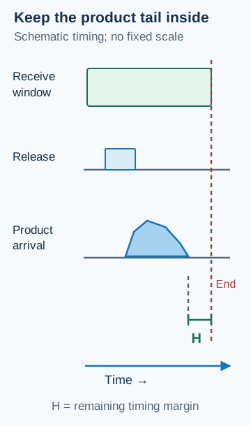
Budget for the trailing product, not just the start of a release signal. The chart has no prescribed time scale.
Use a timing budget to expose missing allowance:
H = t_window − (t_release + t_travel + t_tail + t_allowance).
All terms use milliseconds. t_window runs from the accepted dump permission to the bagger’s latest safe product-arrival time; t_release is the delay to the first product leaving the relevant release gate; t_travel is its travel time; t_tail extends arrival to the final pieces; and t_allowance covers the variability agreed for the trial. H is remaining timing margin. Define the timing boundaries explicitly to avoid counting the same travel twice.
Threshold rule: if H < 0 ms under the observed worst-case product condition, choose a slower bagger cycle or an engineered discharge-path change and revalidate, because the product tail extends beyond the available receiving window. A timing hopper may change coordination, but it does not eliminate product travel or sticking.
As an interface check, ask what happens when a request arrives before the weigher is ready, whether that request is remembered, and what clears it after a stop. Prove the configured answer with the integrator. A stored request that is still valid in one sequence may be stale after the bagger has stopped or changed state. Put those cases on the line integration checklist, along with fault ownership and restart permissions.
Diagnose setup failures without changing everything
Use the failed stage to select the next observation. Preserve the previous recipe and change an approved parameter only when the observation supports it.
Swipe sideways to see the other columns. The first column stays visible.
| Observation | Stage to inspect | Dominant failure mode and prevention |
|---|---|---|
| Few acceptable combinations | Distribution, active heads and ready weights | Starved heads or overly similar partial loads limit choices; record the load snapshot before adjusting feed |
| Selected weight differs from delivered portion | Gate, hopper and chute release | Retained product or late pieces cross bag boundaries; verify actual delivery and contact parts |
| Weight changes after cleaning | Empty indication, reassembly and mechanical clearance | A seated part touches its neighbour or residue remains; complete the prescribed checks before recipe tuning |
| Product appears in the seal area | Receiving window and trailing product | Discharge continues beyond the usable window; review the complete timing budget |
| An out-of-range bag follows a long wait | Exception and forced-discharge logic | Continued cycling masks a failed combination; identify the exception and route affected product correctly |
The downstream weight check is useful evidence, but it should not be the first place a delivery fault becomes visible. For the separate verification role, see checkweighers and metal detectors.
Include residue, cleaning and lost bags in the cost record
Sticky-product handling can add costs through retained product, product cleared at a stop, damaged or contaminated bags, contact-part replacement and cleaning labour. Track each against saleable output, rather than comparing nominal machine cycles alone.
The hidden-cost question is whether a surface or discharge change saves product during running but adds cleaning time or restricts usable bagger output. Record the changeover task, removed product, parts handled, cleaning result and time until an accepted pack is produced. The format changeover checklist provides the adjacent operating record; the packaging bottleneck guide helps locate the constraint when the weigher and bagger wait for each other.
Keep a setup record that can be repeated
Retain the conditions needed to reproduce an accepted run, not only the final target entry. Agree the evidence and acceptance basis through the FAT and SAT process.
Swipe sideways to see the other columns. The first column stays visible.
| Record field | Evidence to retain |
|---|---|
| Product and recipe | Lot, product condition, holding time, contact parts and recipe revision |
| Weighing | Enabled heads, ready-weight snapshot, selected combination, target and approved limits |
| Delivery | Captured portion, residue locations, delayed product and product damage |
| Coordination | Signal roles, request handling, receiving window and observed final arrival |
| Recovery | Tested stop, restart and exception response; affected bags and their disposition |
| Changeover | Removal and cleaning tasks, checks after reassembly, result and sign-off |
Return to the parent packaging section for the bag-forming and downstream decisions that accompany the accepted setup.
Method and sources
Reviewed October 19, 2026. The Ohlson manual is publicly readable through the linked mirror; its issue date is not established. Its main-parameter, theory-of-operation, parameter and signal sections support the mechanism and model-specific head counts. Ishida’s linked OEM documents support the separate contact-part discussion. Equations, assumed weights and trial records are editorial aids; they do not specify firmware, legal limits or production performance. Use the installed machine manuals and approved product trial for operating settings.
Update history
- : First published.
- : Added a manual-based combination example, contact-path review and bagger timing checklist.
Next steps
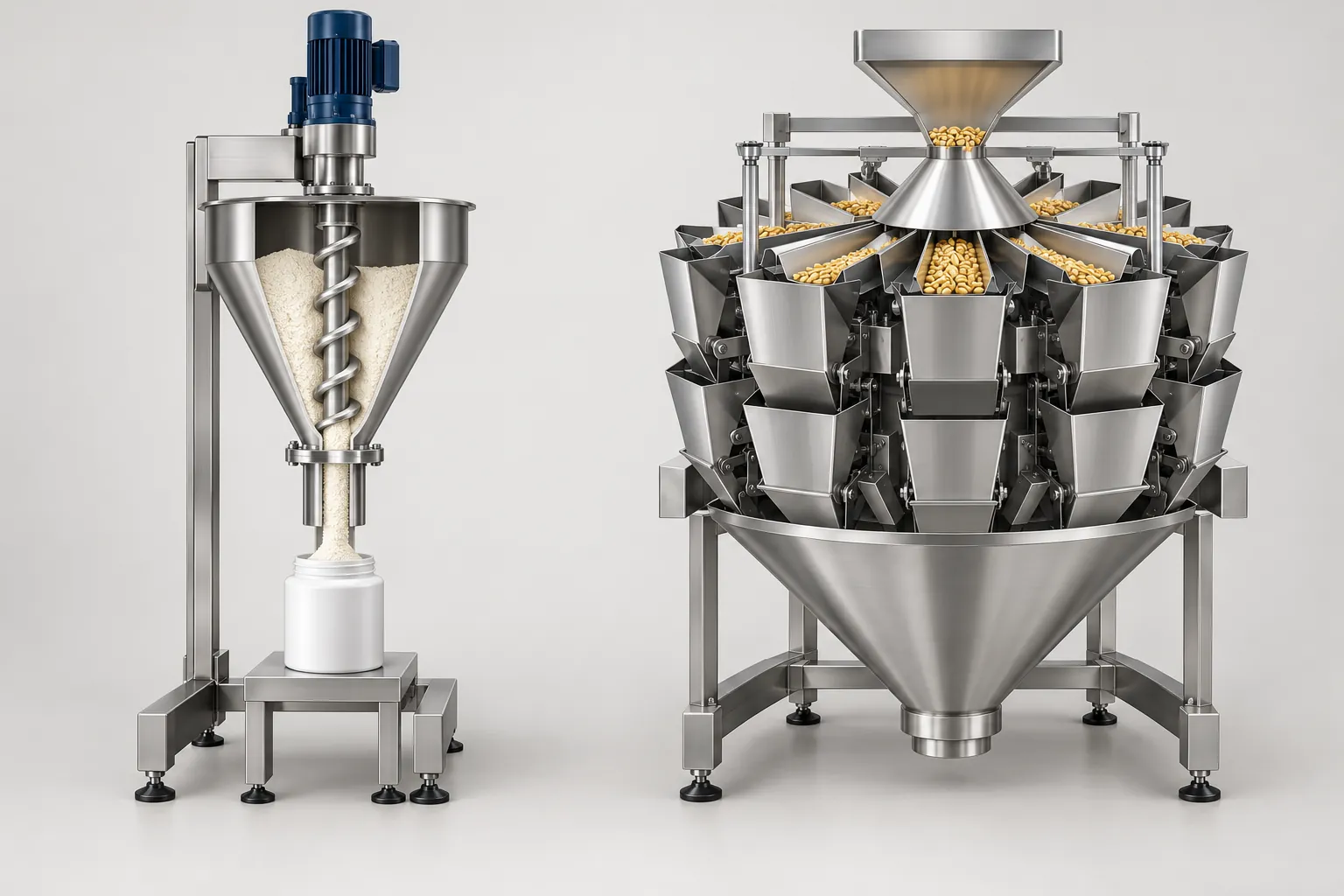
Auger Fillers vs. Multihead Weighers: Matching the Dosing System to the Product
Compare auger fillers and multihead weighers by dosing principle, product flow, fragility, dust, cleaning and mixes, with supplier questions and trial guidance.
Read guide
Packaging Line Integration Checklist: Interfaces to Confirm Before Ordering
Checklist of mechanical, electrical, signal, communication, safety and utility interfaces to settle before ordering a machine for a packaging line.
Read guide
FAT vs. SAT for Packaging Equipment: Defining Acceptance Criteria
Compare factory and site acceptance tests for packaging machines, and learn how to write acceptance criteria that both buyer and supplier can verify.
Read guide