
Net-Weight vs. Volumetric Filling: A Density-Drift Check Before Specifying the Control Method
Use a unit-labelled mass=volume×density worksheet, a control-method matrix and a blank paired-batch trial record before choosing volumetric or net-weight liquid filling.
When a liquid container is specified by mass but metered by volume, any change in product density shifts the delivered weight according to mass = volume × density. Before specifying or replacing the filler, calculate how your worst-case batch density swing translates into mass or fill-level variation, separate the liquid pumping hardware from the metering sensor and cutoff loop, and run a paired-batch trial across both density extremes.
Applies to: Liquid and viscous container filling where batches vary in temperature, aeration or formulation. Excludes dry-powder auger versus multihead selection, mechanical pump-type design, statutory net-quantity compliance advice and universal speed or accuracy ratings.
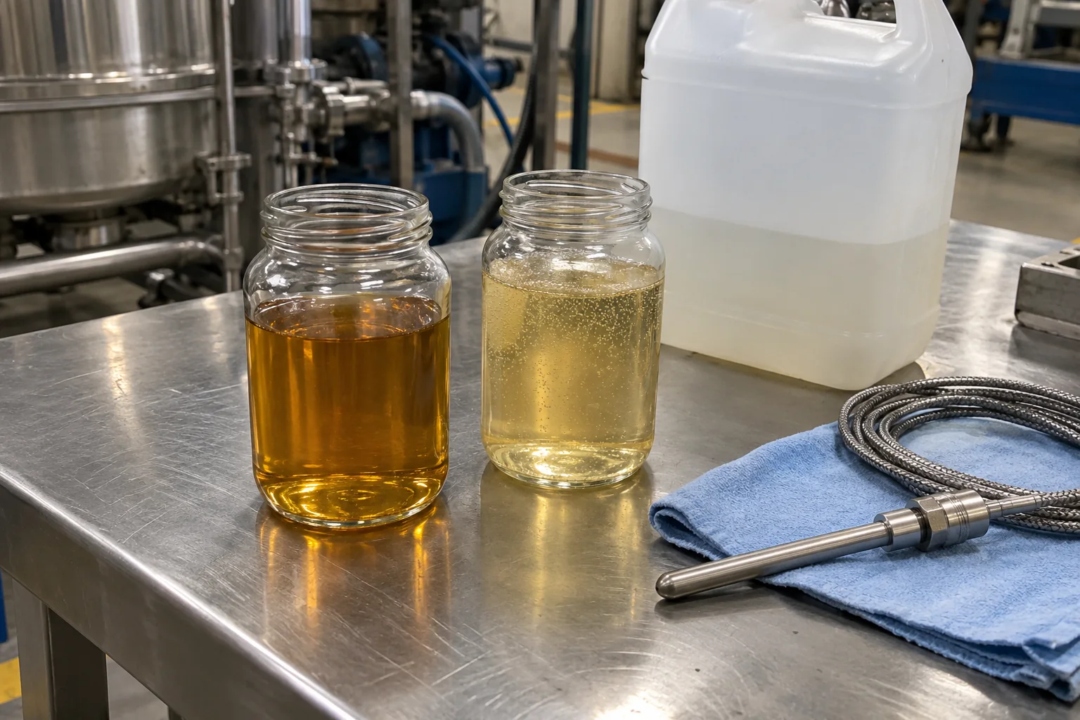
Setting a liquid filler by volume when the finished pack is accepted by mass can waste product or leave containers underweight whenever batch temperature or aeration shifts. Convert your batch density range through mass = volume × density first, then separate how the liquid moves from how the cutoff signal is triggered.
For a liquid fill where density shifts between batches or across a shift, start with a unit-labelled density-conversion worksheet before comparing filler quotes: if a fixed displaced volume held across your measured minimum and maximum product density would push net mass outside your internal pack target, specify either direct mass-based cutoff (load-cell net-weight scales or Coriolis mass flow meters) or a documented recipe-recalibration step between lots. Ideal Pase’s 23 September 2024 comparison of volumetric and net-weight fillers notes that volumetric machines dispense a predetermined liquid volume when viscosity and density remain consistent, whereas net-weight machines weigh the product in each container when density varies or the product is sold by weight. In its 11 June 2026 comparison of inline net-weight and flow-meter systems, Ideal Pase further separates load-cell net-weight filling from flow-meter machines that use either magnetic flow meters (volumetric) or mass flow meters (mass in motion). This guide turns those distinctions into a calculation worksheet, a three-layer control matrix and a blank paired-batch trial record.
Swipe sideways to see the other columns. The first column stays visible.
| Specification or trial input | Source or measurement basis | Why it governs the control choice |
|---|---|---|
Governing pack specification (m or V) |
Product label and QA acceptance sheet (g, kg, mL, L or fl oz) |
Fixes whether acceptance checks delivered net mass, liquid volume or visual fill level |
Minimum and maximum liquid density (ρ_min, ρ_max) |
Lab hydrometer, pycnometer or density meter at actual filling temperatures (g/mL, kg/L or lb/gal) |
Determines how much mass drifts at fixed volume (Δm = V × Δρ) or volume drifts at fixed mass (ΔV = m × Δ(1/ρ)) |
| Temperature and aeration window at the nozzle | In-line or tank temperature log (°C or °F); visual check for entrained air or foam |
Heating, shear in circulation loops and tank drawdown alter effective density during a run |
| Rigid container internal volume and tare variation | Bottle or pail drawing plus weighed empty containers (g and mm neck height) |
Volumetric fills can show uneven liquid levels in variable glass or molded plastic containers; gross-weight checks can be skewed by heavy tare swings |
| Pumping or feeding mechanism | Supplier quote: gravity/pressure tank, piston cylinder or rotary pump | Moves the liquid; does not by itself define whether cutoff is volumetric or gravimetric |
| Metering sensor and cutoff feedback | Supplier quote: mechanical stroke, magnetic flow meter, Coriolis mass meter or load-cell tare scale | Defines what physical quantity triggers valve shut-off and whether density changes are compensated automatically |
Why do mass and volume targets diverge when liquid density drifts?
A volumetric filler holds dispensed volume constant (V = V_0), while a net-weight or mass-flow filler holds delivered mass constant (m = m_0). Because mass, volume and density are tied by the dimensional identity m = V × ρ, holding one variable constant forces the other variable to move whenever product density (ρ) changes between batches, across a temperature swing or after air is whipped into the supply tank.
Ideal Pase’s September 2024 overview states two consequences of this physical relationship: volumetric filling suits liquids with consistent density and viscosity (such as beverages, oils and liquid detergents), and containers filled by volume can still appear unevenly filled when container wall thickness or internal dimensions vary slightly. Qualipak’s liquid and powder comparison (fetched 17 October 2026) likewise notes that because volumetric systems dose by volume rather than direct mass measurement, changes in density, temperature or consistency mean the same volume no longer equals the same net weight.
To check whether density variation matters on your line before requesting equipment quotes, write the three algebraic relations in matching units (g and mL with g/mL, or kg and L with kg/L):
-
Delivered mass from a fixed volumetric setting (
V_0):m = V_0 × ρWhen density shifts fromρ_1(baseline batch) toρ_2(warmer or aerated batch) without recalibrating the volume setting, the net-mass drift is:Δm = m_2 − m_1 = V_0 × (ρ_2 − ρ_1)Expressed as a relative percentage of the baseline massm_1:Δm / m_1 = (ρ_2 − ρ_1) / ρ_1 -
Delivered volume from a fixed net-weight setting (
m_0):V = m_0 / ρWhen a load-cell or Coriolis mass system holds delivered mass constant atm_0while density shifts fromρ_1toρ_2, the liquid volume inside the container changes by:ΔV = V_2 − V_1 = m_0 × (1 / ρ_2 − 1 / ρ_1) -
Volume setting adjustment needed to hold target mass (
m_target) on a volumetric filler:V_adjusted = m_target / ρ_2If the plant keeps a volumetric piston or magnetic flow meter for a mass-specified product, the operator or recipe must shift the target volume fromm_target / ρ_1tom_target / ρ_2whenever density changes, and confirm the adjustment by weighing tared check samples.
Unit-labelled density-conversion worksheet (with an assumed example)
Copy the worksheet below into your engineering file and substitute your own measured lab or floor values. The numerical column is an Assumed example used strictly to show the arithmetic; it is not a measurement from a machine trial or a typical industry value.
Swipe sideways to see the other columns. The first column stays visible.
| Worksheet row | Symbol and formula | Unit convention | Assumed example (illustrative arithmetic only) | Your product entry |
|---|---|---|---|---|
| 1. Nominal target mass on the package | m_target |
g (or kg) |
1,000 g (assumed) |
________ |
| 2. Baseline liquid density at reference condition (Lot A) | ρ_1 |
g/mL (or kg/L) |
1.020 g/mL at baseline condition (assumed) |
________ |
| 3. Shifted liquid density at comparison condition (Lot B) | ρ_2 |
g/mL (or kg/L) |
0.995 g/mL after warming or aeration (assumed) |
________ |
4. Volumetric setting calibrated to hit m_target on Lot A |
V_0 = m_target / ρ_1 |
mL (or L) |
1,000 / 1.020 = 980.4 mL (assumed) |
________ |
5. Actual mass delivered on Lot B if V_0 is left unchanged |
m_2 = V_0 × ρ_2 |
g (or kg) |
980.4 × 0.995 = 975.5 g (assumed) |
________ |
6. Uncompensated mass drift under fixed volume V_0 |
Δm = m_2 − m_target |
g and % of m_target |
−24.5 g (−2.45% relative to 1,000 g, assumed) |
________ |
7. Actual volume delivered on Lot B if a net-weight filler holds m_target |
V_2 = m_target / ρ_2 |
mL (or L) |
1,000 / 0.995 = 1,005.0 mL (assumed) |
________ |
8. Volume and headspace shift under fixed net weight m_target |
ΔV = V_2 − V_0 |
mL (check against bottle overflow/headspace) |
+24.6 mL higher liquid volume in the bottle (assumed) |
________ |
Takeaway: A percentage change in liquid density produces the exact same percentage change in delivered mass when volume is held constant (Δm / m_1 = Δρ / ρ_1). Conversely, holding net mass constant when density drops increases the liquid volume inside the container (V_2 > V_1), which must fit within the container’s available headspace.
How do pumping hardware, flow meters and load-cell feedback differ?
Supplier brochures frequently contrast “piston fillers,” “flow-meter fillers” and “net-weight fillers” as if they were three mutually exclusive ways to move liquid. In practice, a liquid filler combines three separate engineering choices:
- Liquid propulsion (how product is moved): gravity from an elevated tank, a pressurized manifold (such as the built-in pressurized tank Ideal Pase notes on DTM PureFil systems for more viscous fluids), a positive-displacement piston cylinder, or a rotary pump (gear, lobe, peristaltic or centrifugal).
- Primary sensed variable (what the machine measures during the fill): swept mechanical displacement (
mLper stroke or pump revolution), fluid velocity converted to volume (mLvia a magnetic flow meter), inertial mass flow (gvia a Coriolis mass flow meter), or static/dynamic force on the container support (gvia a strain-gauge or digital load cell). - Valve cutoff loop (how the dose ends): mechanical end-of-stroke, pulse totalizer cutoff, or closed-loop two-stage (bulk + dribble) valve shut-off when the tare-corrected scale reaches target weight.
All-Fill’s volumetric piston-filler product documentation (library copy fetched 6 October 2026; verified live 17 October 2026) illustrates mechanical volumetric displacement: a piston retracts to draw product into a cylinder and advances to dispense a repeatable volume per cycle (for example, its semi-automatic single-head Model 305 lists a stated fill range from 0.25 oz to 87 oz per cycle across liquids, creams, pastes and sauces). The cylinder stroke sets a geometric volume; it does not sense changes in fluid density. For a detailed look at cylinder and rotary-pump hardware, see the piston and pump filling comparison.
Ideal Pase’s June 2026 technical blog comparing Ideal Pase inline net-weight fillers with DTM Packaging flow-meter machines clarifies why “flow-meter filling” cannot be lumped into a single volumetric column: DTM’s flow-meter fillers use either magnetic or mass flow meters to measure product volume or mass in motion. Magnetic flow meters measure volumetric flow of conductive liquids, whereas mass flow meters (Coriolis type) measure mass directly in motion. Meanwhile, Ideal Pase’s inline net-weight fillers place containers on load cells to dispense based on actual weight in the container, which Ideal Pase notes is unaffected by surface foam and suited to pints, pails, drums and totes.
In dry-powder dosing, Per-Fil Industries’ comparison of volumetric versus fill-by-weight auger fillers (live fetch 17 October 2026) describes the same control-loop split: open-loop volumetric dosing runs a fixed number of auger revolutions or a timed fill, whereas closed-loop gravimetric filling uses an integrated scale with a high-speed bulk stage followed by a slow dribble stage to stop at target weight. While powder auger mechanics belong in the auger filler and multihead weigher guide, that two-stage bulk-and-dribble cutoff principle also explains why load-cell liquid fillers require weighing stabilization time on each container.
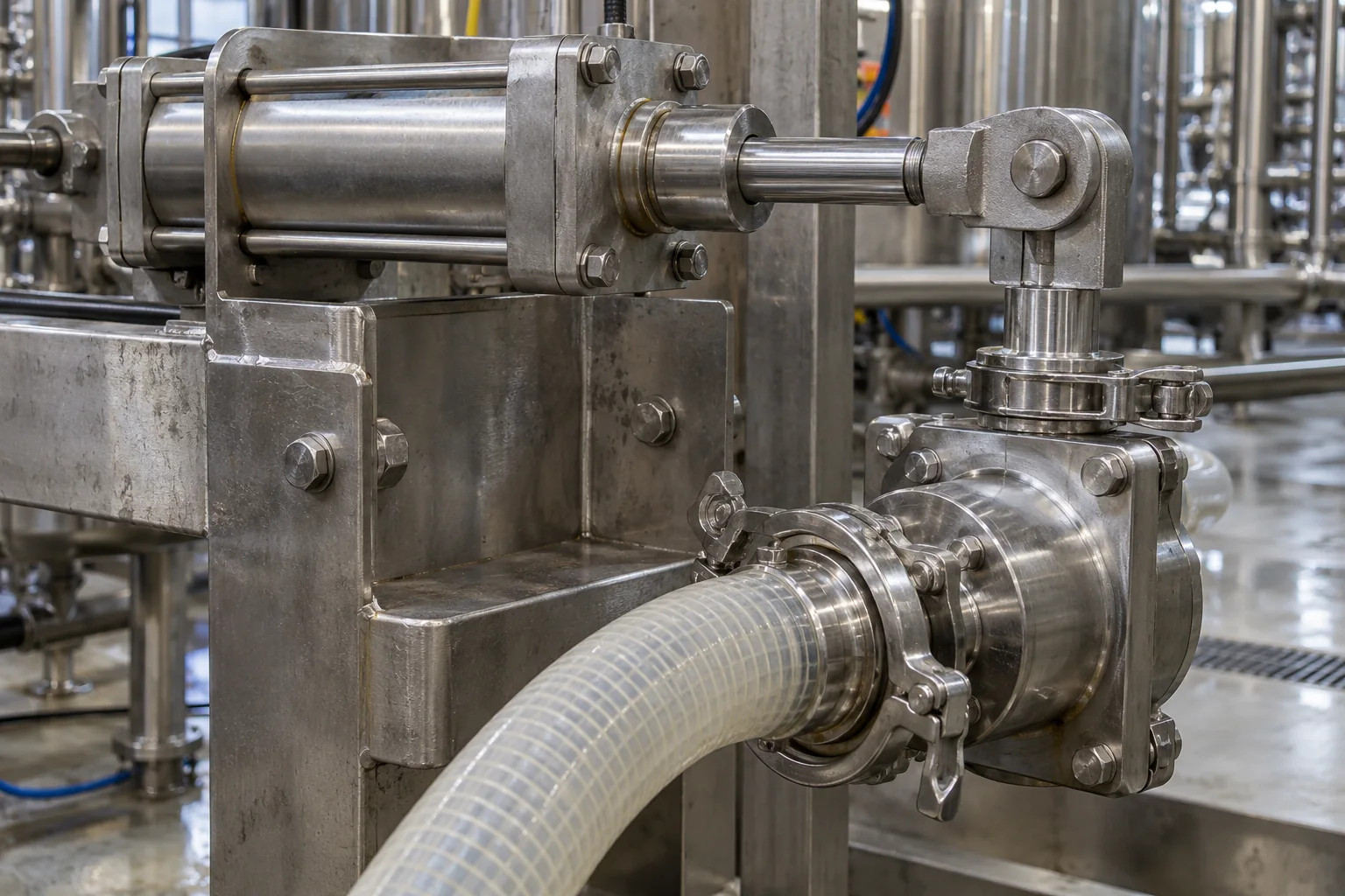
Control-method separation matrix for liquid filling
Use the matrix below to classify each supplier quotation by what the machine actually measures and how it reacts when product density, aeration or container tare weight changes. Vendor headline accuracy percentages (such as Ideal Pase’s stated ±0.1%–0.5% for net-weight or ±0.25% one-sigma for flow-meter water-like fills, or Per-Fil’s powder percentages) are excluded from the matrix because they depend on container size, fluid rheology and cycle rate; verify performance on your own liquid under matched trial conditions.
Swipe sideways to see the other columns. The first column stays visible.
| Control architecture | Typical propulsion hardware | Primary quantity sensed | Response when liquid density (ρ) drops (−Δρ) |
Response when surface foam or entrained air is present | Effect of container tare-weight variation | What to confirm with the supplier |
|---|---|---|---|---|---|---|
| Mechanical volumetric displacement (piston or timed/counted rotary pump) | Piston cylinder with changeover valve, or gear/lobe/peristaltic pump | Swept cylinder volume or pump shaft revolutions (V) |
Delivered volume stays near V_0 (unless gas compresses); delivered net mass drops by V_0 × Δρ |
Entrained gas pockets occupy cylinder volume and reduce delivered mass; surface foam in the bottle can overflow | Does not affect dispensed volume; wall-thickness variation alters visual fill height in clear bottles | Stroke adjustment resolution, check-valve seating on particulates, and how operators recalibrate stroke when batch density shifts |
| Volumetric flow meter (magnetic flow meter) | Gravity manifold, pressurized tank or transfer pump through a shut-off nozzle | Fluid velocity through a known bore integrated over time (V) |
Delivered volume stays near V_0; delivered net mass drops by V_0 × Δρ unless a density offset is entered |
Entrained gas bubbles passing the electrodes count as liquid volume and reduce delivered mass | Does not affect metered volume; container geometry variation still shifts visual fill level | Minimum fluid electrical conductivity required by the meter, straight-pipe run, and whether air entrainment occurs during tank drawdown |
| In-motion mass flow meter (Coriolis mass flow meter) | Pressurized tank or pump manifold feeding shut-off nozzles | Direct inertial mass flow (m) and tube resonant density (ρ) in motion |
Holds delivered mass near m_0; dispensed liquid volume increases (m_0 / ρ_2) |
Measures mass flow directly, though two-phase slugging or severe gas entrainment can disturb tube oscillation | Independent of container tare weight because mass is measured inside the meter tube before the nozzle | Allowable pressure drop at required flow rate, shear/viscosity limits through the meter tubes, and zero-point stability during CIP thermal cycling |
| Load-cell net-weight feedback (platform or neck-clamp scale per station) | Gravity, pressure, pump or piston supply with two-stage (bulk + dribble) shut-off valve | Static and dynamic weight (m) of product accumulating in the tared container |
Holds delivered net mass near m_0; dispensed liquid volume increases (m_0 / ρ_2) |
Unaffected by surface foam inside the container; measures actual mass collected on the scale | Requires per-container auto-tare before opening the valve; un-tared gross weighing transfers tare variation into net fill error | Auto-tare sequence time, bulk-to-dribble transition point, in-flight column compensation, and mechanical isolation from conveyor vibration |
Takeaway: Do not treat “flow meter” as a synonym for volumetric filling, and do not assume a piston or pump precludes weight control. Ask every bidder to name the propulsion device, the sensor that generates the cutoff signal, and whether each container is individually tared.
When can a volumetric filler stay on a mass-specified product?
Replacing a volumetric piston or magnetic flow-meter filler with a multi-station load-cell or Coriolis machine is not the only engineering response when a product is sold or tracked by weight. A volumetric control loop can remain suitable for a mass-specified pack when three conditions are verified together:
- In-batch density drift (
Δρwithin a single production run) is small relative to your internal mass tolerance: For example, if product temperature is jacket-controlled and the feed tank is deaerated,ρmay vary mainly between formulated batches rather than minute by minute. - Between-batch density differences are handled by a documented calibration check: Before starting a new batch, the operator measures batch density (or weighs a fixed set of startup containers on an offline tared check-scale) and adjusts the piston stroke or flow-meter pulse target to
V_adjusted = m_target / ρ_batch. - Downstream checkweighing catches uncompensated drift: An inline checkweigher downstream of the capper weighs 100% of finished packs and rejects containers that drift outside limits—provided container tare weight variation does not mask the net product weight. See the checkweigher and metal detector guide for how downstream gross-weight inspection differs from at-nozzle net-weight control.
Conversely, volumetric control with manual check-weighing becomes difficult to sustain when:
- Product density changes continuously during a single run (for instance, a hot-fill sauce cooling in an unjacketed hopper, a whipped or aerated lotion whose air content shifts with agitator exposure, or a shear-thinning chemical recirculating through a pump bypass).
- Container tare weight varies widely (such as heavy glass jars, blow-molded jugs or reconditioned drums and totes) so that a downstream gross checkweigher cannot separate container weight from product weight.
- High unit product cost or large container volume (pails, drums, totes) makes overfilling to cover density swings more expensive than the cycle-time penalty of load-cell bulk-and-dribble weighing.
How to run a paired-batch density-drift trial before changing the filler
Before approving a capital project or signing a factory acceptance plan, test the candidate control method across the real density extremes of your product rather than running water or a single room-temperature drum. A single-condition run only checks short-term repeatability (σ at fixed ρ); it cannot show how the filler behaves when density shifts from Lot A to Lot B.
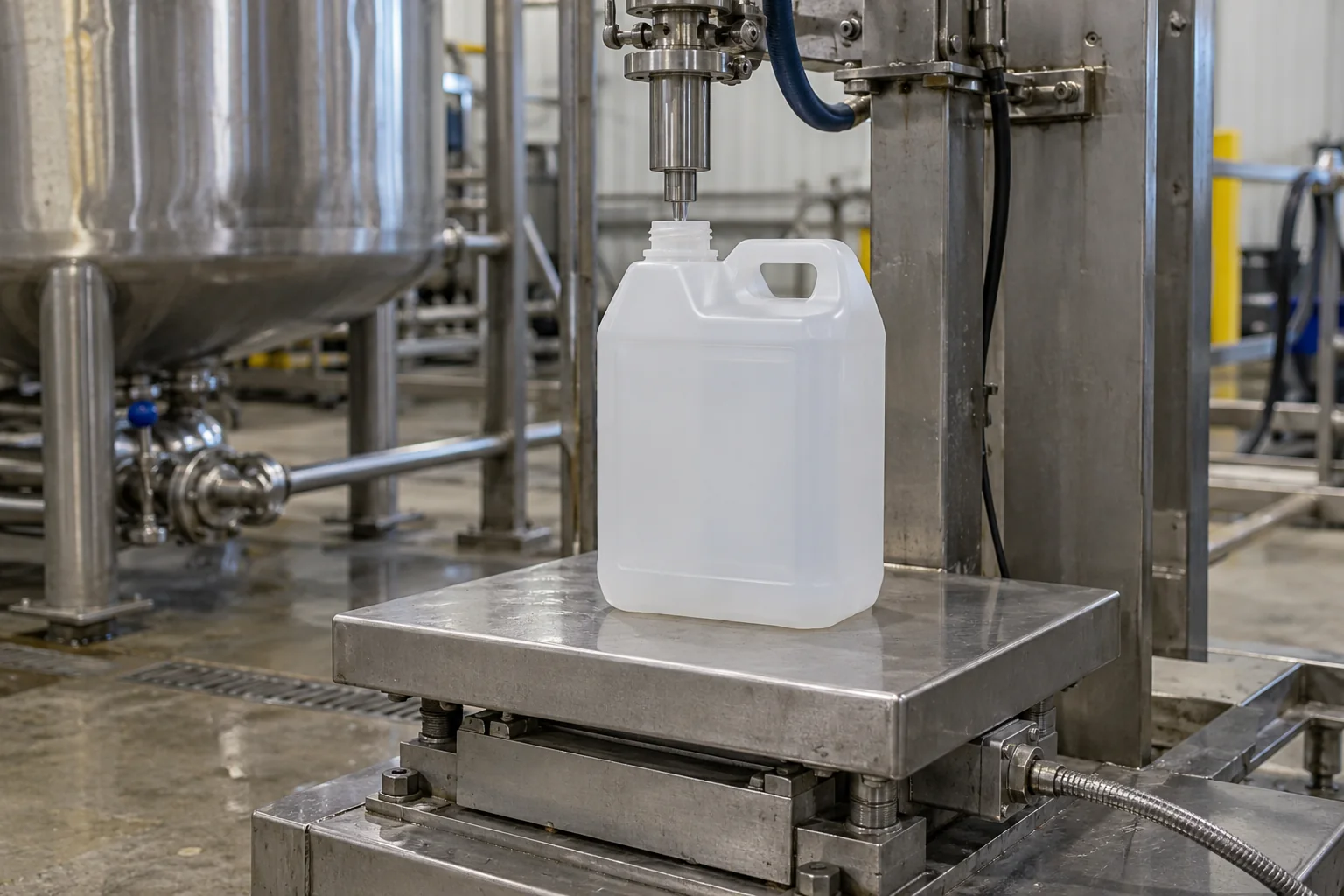
When setting up the trial station, inspect the physical boundaries around the container and nozzle:
- Nozzle-to-container clearance: On a load-cell filler, neither the filling nozzle, a diving-nozzle guide, a drip tray nor a neck guide may touch the container while the scale takes its tare or cutoff reading.
- Pre-weigh and post-weigh tare: Number 10 to 30 consecutive empty containers for each batch, weigh each empty container on a calibrated reference scale before filling, and weigh the filled container afterward so true delivered net mass (
m_delivered = m_gross − m_tare) is recorded alongside whatever reading the filler HMI displays. - Locked recipe between Batch A and Batch B: To test whether the machine compensates for density automatically, run Batch A (for example, cold or freshly mixed deaerated product) and Batch B (warm, recirculated or aerated product at the opposite end of your specification window) without touching the filler’s target setting between the two batches.
Copyable paired-batch density-drift trial record
Use one copy of this record per machine configuration. You can also download the blank paired-batch density-drift trial record as CSV. Leave any unmeasured cell blank (________) or write “Unknown / verify on the unit”—never backfill assumed numbers into a trial record.
Swipe sideways to see the other columns. The first column stays visible.
| Record field | Batch A (baseline / cold / deaerated condition) | Batch B (comparison / warm / aerated / end-of-run condition) | Supporting record |
|---|---|---|---|
| Trial date, liquid name and lot identifier | ________ | ________ | Batch record |
| Observed condition (clear, viscous, foamy, aerated or settled) | ________ | ________ | Visual log at feed tank |
Measured product temperature at nozzle inlet (°C or °F) |
________ | ________ | Calibrated thermometer log |
Measured liquid density at filling temperature (g/mL, kg/L or lb/gal) |
________ | ________ | Hydrometer, pycnometer or lab density record |
| Container specification, nominal capacity and tare-weight range | ________ | ________ | Container drawing and empty-container scale log |
| Pumping or feeding mechanism fitted (gravity, pressure, piston or rotary pump) | ________ | ________ | Quoted machine configuration |
| Metering and cutoff control loop (stroke stop, magnetic flow meter, Coriolis mass meter or load-cell tare scale) | ________ | ________ | Controls specification |
| Cutoff stages and recipe settings (single-stage, bulk/dribble, suck-back or diving nozzle) | ________ | ________ | HMI parameter sheet |
| Target fill specification and governing acceptance basis (net mass, liquid volume or visual fill height) | ________ | ________ | Project specification |
Calculated expected drift from m = V × ρ before running (g, kg or mL) |
________ | ________ | Density-conversion worksheet |
| Sample size weighed and tared individually (for example, 10 to 30 consecutive containers) | ________ | ________ | Individual check-scale log |
Observed delivered net mass range and mean (g, kg or lb) |
________ | ________ | Tared check-scale printout |
Observed liquid fill-height range relative to neck or label datum (mm) |
________ | ________ | Gauge or ruler check on rigid containers |
| Observed foam, air pockets, nozzle drip or tare-platform contact during cutoff | ________ | ________ | Station observation log |
| Cycle time, good packs completed and manual adjustments between Batch A and Batch B | ________ | ________ | Run timing log |
| Unresolved drift, owner and next verification step | ________ | ________ | Action register |
What to carry into your RFQ and factory acceptance test
Once the density-conversion worksheet and paired-batch record show whether your product needs volumetric repeatability, in-motion mass metering or load-cell net-weight cutoff, lock those conditions into your procurement documents so suppliers quote on identical assumptions:
- State both the governing quantity and the density window in the RFQ: In Section 1 (Product) and Section 2 (Package) of the packaging machine RFQ checklist, give the nominal fill target with its unit (
gormL), the minimum and maximum liquid density across your operating temperature and aeration window, and the empty-container tare weight range. - Require suppliers to name the three control layers separately: Ask each bidder to specify (a) the liquid propulsion mechanism, (b) the primary flow or weight sensor, and (c) how the cutoff valve compensates for in-flight liquid after the stop signal fires.
- Write a two-condition acceptance test into the FAT/SAT plan: When drafting test protocols with the FAT and SAT guide for packaging equipment, specify whether acceptance runs will use actual product at two temperatures/densities or a single conditioned lot, and agree in advance how empty containers are tared and how many consecutive packs are weighed.
- Place the filler in the full line context: If switching from volumetric indexing to load-cell bulk-and-dribble weighing increases dwell time per container, check how many filling heads are required so the filler does not become the line constraint; use the packaging machine types overview to coordinate upstream feeding, capping and labeling rates.
Scope limits
This guide provides a dimensional calculation (m = V × ρ), a control-architecture matrix and a paired-batch trial record for liquid and viscous container filling. It does not provide legal or statutory net-contents compliance advice, maximum allowable variation (MAV) tables, or overfill targets; consult qualified regulatory specialists and applicable weights-and-measures standards for legal-for-trade requirements. It does not rank machinery manufacturers, verify vendor accuracy or speed claims, or replace a trial on your own liquid and containers.
Method and sources
Updated October 2026. Compiled from public manufacturer technical pages and standard dimensional relationships (mass = volume × density). We did not run a physical filling trial or test any named machine model. Numerical entries in the density-conversion worksheet are explicitly marked Assumed example for arithmetic illustration only. Photographs show generic unbranded containers, a piston-valve sub-assembly and a nozzle-over-scale setup; they do not depict a named manufacturer’s tested installation.
- Ideal Pase, Choosing the Right Liquid Filling Technology: Net Weight vs. Flow Meter Systems, published 11 June 2026, library copy fetched 8 October 2026 and live-fetched 17 October 2026. Distinguishes load-cell inline net-weight fillers from DTM Packaging flow-meter machines using magnetic (volumetric) or mass flow meters. Vendor accuracy figures (
±0.1%–0.5%,±0.25%one sigma) remain supplier statements to verify under project conditions. - Ideal Pase, Understanding Volumetric and Net Weight Fillers: What’s Right for Your Business?, published 23 September 2024, cached 11 October 2026 and live-fetched 17 October 2026. Describes consistent-density volumetric liquid filling, visual fill-level variation when container dimensions vary, and net-weight filling when density varies or product is sold by weight.
- All-Fill Inc., Volumetric Piston Filling Machines, library copy fetched 6 October 2026 and live-fetched 17 October 2026. Describes volumetric piston displacement across liquids, creams and pastes, including semi-automatic Model 305 (stated 0.25 oz to 87 oz per cycle).
- Per-Fil Industries, Volumetric vs. Fill-by-Weight Auger Fillers: Which is Best?, cached 11 October 2026 and live-fetched 17 October 2026. Used only to contrast open-loop revolution/timed dosing against closed-loop scale feedback with bulk-and-dribble cutoff; dry-powder accuracy claims are not transferred to liquids.
- Qualipak Machinery, Net Weight vs. Volumetric Filling: How to Choose, live-fetched 17 October 2026. Notes that density and temperature shifts alter the mass of a fixed volume and separates measurement basis from product feeding hardware.
Update history
- : First published.
Next steps
Piston vs. Pump Filling: Questions to Ask Before Choosing
Compare piston and pump filling systems by viscosity, particulates, shear, cleaning, product changes, containers and metering method, with supplier questions.
Read guide
Packaging Machine RFQ Checklist: Information Suppliers Need
A reusable blank RFQ template for packaging machines in nine sections, with the reason suppliers need each item and a list of commonly missed details.
Read guide
FAT vs. SAT for Packaging Equipment: Defining Acceptance Criteria
Compare factory and site acceptance tests for packaging machines, and learn how to write acceptance criteria that both buyer and supplier can verify.
Read guide
Checkweighers vs. Metal Detectors: Different Inspection Jobs
A checkweigher verifies package weight and a metal detector controls metal contamination. See why one cannot replace the other and how to plan rejects and records.
Read guide