
Induction Cap Sealing: Air Gap, Foil Liner and Torque
An induction seal fails when the foil misses the land. Match the head's printed gap, the liner's layers, and the cap's torque row before raising power.
Set the sealing head to the gap callout printed for that head, torque the cap inside the handbook row for its size, and find output between the first complete seal and one point below the first overheated liner. A multilayer liner also has to melt wax into the pulpboard. A single-piece liner does not.
Applies to: Setup checks for an induction cap sealer using a foil liner. Figures are from the Enercon Cap Sealing Handbook retrieved 20 October 2026. Exact torque, frequency, and output still come from the cap maker and the installed manual.

An induction seal fails when the foil never meets the land. Low torque and high torque both leave an air gap, and that gap overheats the liner instead of bonding it.
Use the gap callout printed for that sealing head, the torque row for that cap size, and the liner’s own layers. Then set output from the first complete seal up to one point below the first sign of overheating. A cap that looks closed is not evidence the foil bonded.
Seeing a cap in place is a different check from a hidden foil bond. The inspection equipment guide keeps those questions apart. Where the sealer sits among fillers and closers is the machine-types overview. This page is the sealer setup.
The photograph shows a head over caps. It is not a measured gap and it is not an Enercon machine.
Which miss ruins the seal?
The Enercon Cap Sealing Handbook, retrieved 20 October 2026, separates the head, the cap, and the liner. The PDF was created 1 March 2011. Treat the numbers as that handbook’s print, not as a setting for every brand of sealer.
Swipe sideways to see the other columns. The first column stays visible.
| Check | What the handbook prints | Dominant failure mode and prevention |
|---|---|---|
| Tunnel head gap | Side-view callout: 1/8 in. to 1/4 in. (3 to 6 mm) | Using the flat-head 1/8 in. callout as if the tunnel diagram had no range. Read the callout on the head you mounted. |
| Flat head gap | 1/8 in. gap recommended. Distance D must be equal side to side and back to front. | A gauge that changes the gap when it is removed. Step 5 says the fit should be snug with no change when the gauge comes out. |
| Deep tunnel | The liner must be aligned as shown. That diagram does not print the 1/8 to 1/4 in. range. | Copying the tunnel inch range onto a deep tunnel. The page does not give it. |
| Cap torque | Too low or too high usually leaves an air gap between the lip and the liner. The polymer then cannot fill the gap, and the liner usually overheats. | Treating a tighter cap as a better seal. The handbook says both directions open the same gap. |
| Land and cap seat | The land should be wide and rigid enough for the pressure and heat. A thin land, a fall-away, a protrusion, or a cocked cap leaves a gap that can overheat the liner. A cocked cap can also jam the container under the head. | Raising power to hide a land defect. The handbook says those defects can be seen on the land before the container is capped. |
| Metal under the head | No metal guide rails beneath the sealing head. The note for the “1” sealing head says to set it up like the flat head, then skew it for the cap size. | Leaving a metal rail in the field. The note forbids it. |
How far apart are the printed gaps?
The tunnel side view spans a factor of two:
(1/4) / (1/8) = 2
The millimetre pair on the same callout is the same ratio: 6 / 3 = 2. The top of that printed range is twice the bottom. The handbook does not print a field-strength formula for that doubling. It only prints the range.
The flat-head callout is the single value 1/8 in. recommended, with D equal side to side and front to back. Quick setup is six steps: level and center the head; fill two containers to production weight; put one at each end of the head; put a thickness gauge on each cap; lower the head onto the gauge until removing the gauge does not change the gap; align the guide rails so containers stay centered.
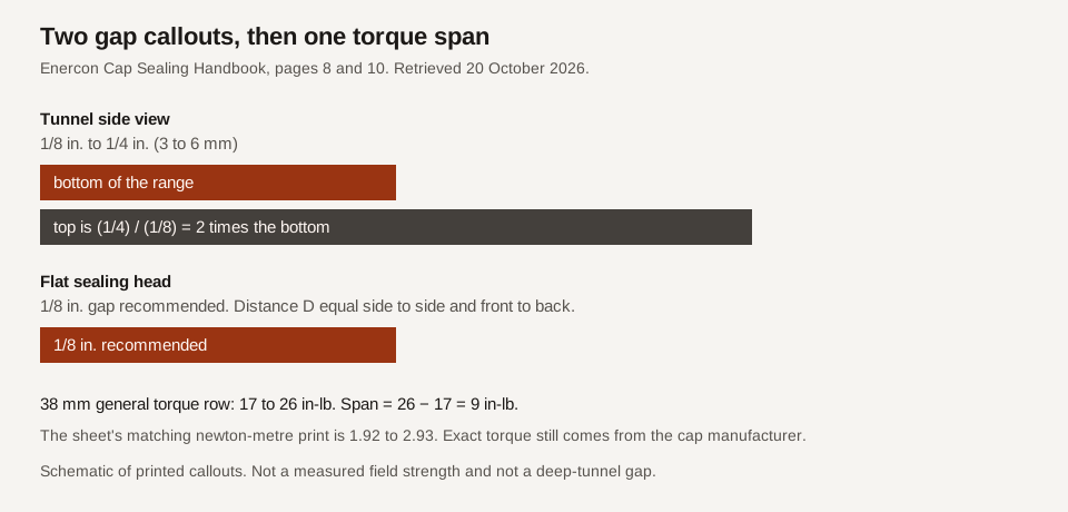
The bars are the handbook’s callouts. The 2× mark is (1/4) divided by (1/8). It is not a measured loss of sealing power.
What the foil liner has to do
A multilayer liner has four components: pulpboard, wax, foil, and polymer. In the field, the foil heats until the polymer melts and flows around the land, the wax melts and is absorbed into the pulpboard or similar backing, and the polymer cools into the seal.
A single-piece liner has two components: foil and polymer. The foil heats, the polymer flows around the land, and the polymer cools. There is no wax-into-pulpboard step.
The handbook’s frequency note follows that split. Higher frequency concentrates heat on the outside edge, which it calls beneficial for one-piece liners. Lower frequency heats more uniformly, which it calls desirable for a wax-bonded two-piece inner seal. It does not print a frequency number.
A good seal, in the same handbook, has adhesion around the whole circumference, minimum wrinkling, and no darkening of a multilayer cap that would show overheating. A poor seal comes from output too low, line speed too high, or a misaligned head. Overheating comes from output too high or line speed too slow: wrinkling, melting into the lip, a burned smell, and, on a multilayer liner, discoloration or burning of the pulpboard.
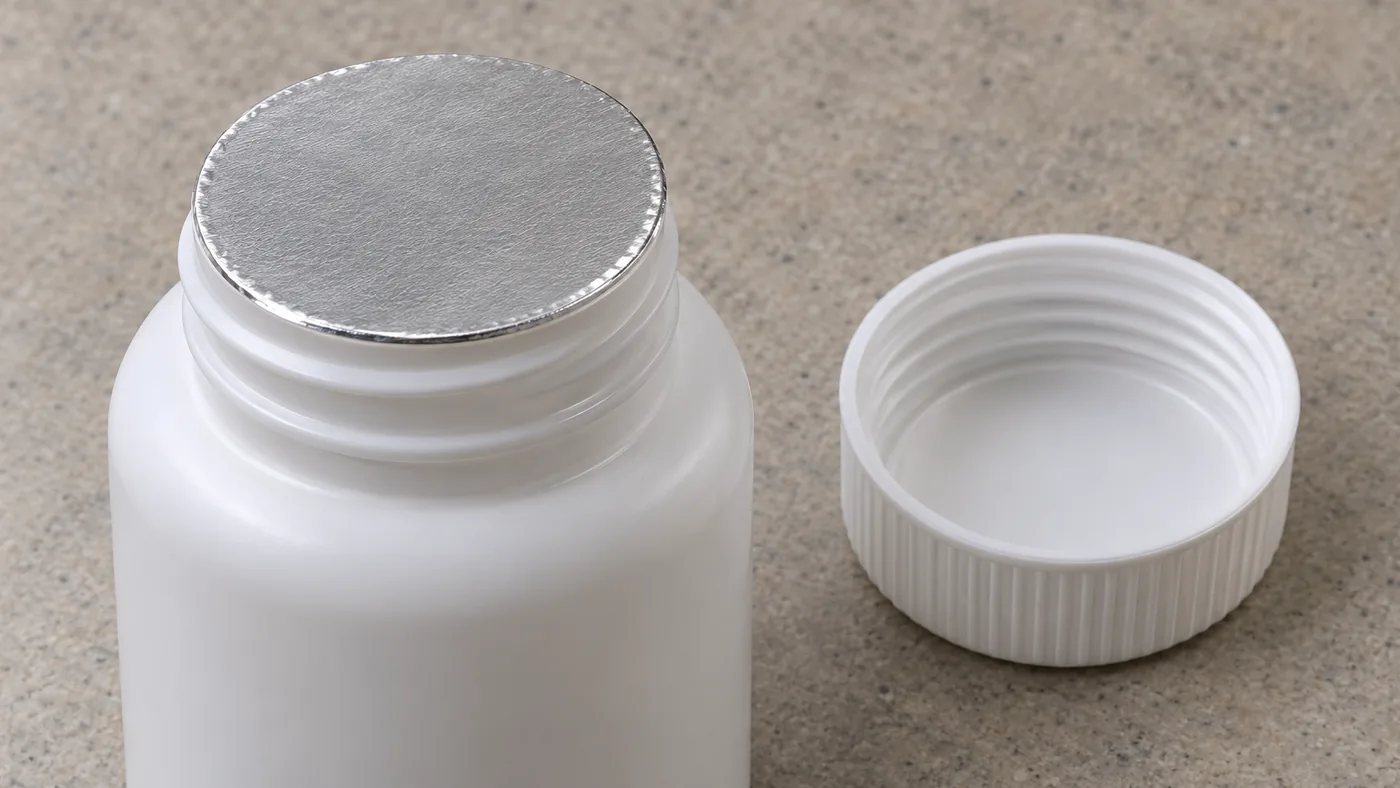
The disk is the liner. The cap beside it is not evidence the disk has bonded.
Where the torque row starts and stops
The handbook calls the table a general rule of thumb and says exact torque comes from the cap manufacturer. Both ends of a row matter. For a 38 mm cap the printed row is 17–26 in./lbs, also printed as 1.92–2.93 nm.
Span = 26 − 17 = 9 in-lb
The printed newton-metre ends differ by 2.93 − 1.92 = 1.01. A reading under 17 or over 26 is outside that general row. It is not automatically a failed cap until the cap manufacturer’s number is the one in use.
Swipe sideways to see the other columns. The first column stays visible.
| Cap size | Printed torque |
|---|---|
| 15 mm | 6–9 in./lbs (0.68–1 nm) |
| 18 mm | 7–10 in./lbs (0.79–1.13 nm) |
| 20 mm | 8–12 in./lbs (0.9–1.35 nm) |
| 22 mm | 9–14 in./lbs (1–1.58 nm) |
| 24 mm | 10–16 in./lbs (1.13–1.8 nm) |
| 28 mm | 12–18 in./lbs (1.35–2.03 nm) |
| 33 mm | 15–25 in./lbs (1.69–2.82 nm) |
| 38 mm | 17–26 in./lbs (1.92–2.93 nm) |
| 43 mm | 18–27 in./lbs (2.03–3.05 nm) |
| 48 mm | 19–30 in./lbs (2.14–3.38 nm) |
| 53 mm | 21–36 in./lbs (2.37–4.06 nm) |
| 58 mm | 23–40 in./lbs (2.59–4.51 nm) |
| 63 mm | 25–43 in./lbs (2.82–4.85 nm) |
| 70 mm | 28–50 in./lbs (3.16–5.65 nm) |
| 83 mm | 40–60 in./lbs (4.51–6.78 nm) |
| 89 mm | 45–65 in./lbs (5.08–7.34 nm) |
| 100 mm | 50–70 in./lbs (5.65–7.90 nm) |
| 110 mm | 52–73 in./lbs (5.87–8.25 nm) |
| 120 mm | 55–75 in./lbs (6.21–8.47 nm) |
How the output window is marked
Page 11’s procedure, after the head, the speed, the package, and the torque are already right:
- Start at minimum output and run one container.
- If there is no seal, raise output in steps of 5–10% until the seal is partial, then in steps of 1–2% until it is complete. If the first result is already partial, use only the 1–2% steps. That complete seal is the minimum set point.
- Raise output in steps of 1–2% until the liner or cap shows overheating, then lower output by 1%. That is the maximum set point.
- Test inside the window for the production output. Run a group that fills the head and check that the output meter stays constant and every container matches.
- Record minimum, maximum, production output, line speed, cap, liner, and container. Repeat for each package.
Maximum = P − 1
P is the first output, in percent, that shows overheating. The minus 1 is the handbook’s step. P itself is not printed.
Worksheet, not a recorded run: the first complete seal is at 40%, and the first overheating is at 48%. Then the maximum is 48 − 1 = 47, and the window width is 47 − 40 = 7 percentage points. The 40 and the 48 are assumptions so the subtraction can be checked.
Rules of thumb
If the head is the tunnel in the side-view callout, the printed gap is a range, 1/8 in. to 1/4 in., not the flat head’s single 1/8 in. If D is not equal side to side and front to back, the page’s own note says that is not the optimum setup. If torque is outside the row for that millimeter size, expect the air gap the handbook describes, then confirm the number with the cap manufacturer. If the liner is single-piece, do not wait for wax to disappear into pulpboard; that step belongs to the multilayer liner. If output is still at the first sign of burning, it is one point above the maximum the procedure names. Glass with a dry product is the case the handbook says can always be sealed. Liquids in glass are the case it sends to the inner-seal supplier.
A seal that is already on the container and still leaks is a different investigation, in seal defect investigation. Changing cap size is a format change; the format changeover checklist is the record for that, and proving the window on your own containers belongs in factory and site acceptance.
Common questions
What air gap does the handbook print?
Two callouts. The tunnel side view is 1/8 in. to 1/4 in. (3 to 6 mm). The flat sealing head is 1/8 in. recommended. The deep-tunnel diagram says to align the liner as shown and does not print that inch range.
Does more cap torque make a stronger induction seal?
Not in this handbook. Torque that is too high and torque that is too low both usually leave an air gap the polymer cannot fill, and that gap usually overheats the liner. The table is a general row. The cap manufacturer has the exact number.
Does a one-piece foil liner use wax?
No. The handbook’s single-piece liner is foil and polymer. Wax absorbed into pulpboard is a step of the four-part multilayer liner.
Methods and sources
Gap callouts, the six setup steps, the equal-D note, the “1” sealing head note, and the metal-rail note are page 10 of the Enercon Cap Sealing Handbook. Liner layers are page 6. Land, protrusion, and cocked-cap notes are page 7. The torque table and the air-gap sentence are page 8. The operating-window steps are page 11. The frequency sentence and the dry-glass sentence are the rules of thumb on page 1. The file’s creation date is 1 March 2011, and the copy used here was retrieved 20 October 2026 from the PDF linked below. The 40% and 48% outputs are worksheet assumptions. No line was assigned a production output.
References
- Enercon Cap Sealing Handbook — Enercon Industries Corporation
Update history
- : First published.
- : Added the handbook's gap callouts, liner layers, torque span, and operating-window steps.
Next steps
Packaging Inspection Equipment: Match the Inspection Job
Match checkweighers, metal detectors, X-ray, vision and leak tests to packaging defects, then plan inspection positions, samples and rejection evidence.
Read guide