
Checkweigher and Metal Detector Combo Systems: Layout and Rejects
Plan checkweigher and metal detector combo systems around station order, pack transfers, reject routing and metallized-film detection limits.
Specify a checkweigher and metal detector combo system as an integrated pack-tracking and rejection arrangement. Establish detector placement from the contamination risk and actual film, preserve stable weighing transfers, and prove that each reject reason reaches the correct secured destination. A shared interface does not prove either inspection performance or successful removal.
Applies to: Engineering review of conveyor-based combo systems for individual finished packs. Covers layout, transfers and acceptance evidence; product-specific sensitivity, weight limits and controller settings require the applicable machine documentation and quality plan.

A compact inspection station can still release the wrong pack if tracking or rejection fails. Checkweigher and metal detector combo systems need a verified in-line sequence, stable transfers and a reject route that preserves the reason for removal.
Set up a combo system around the complete pack journey: detection, weighing, tracking, removal and disposition. Review the actual product and packaging before fixing the detector position; then check whether the weigh belt supports the pack independently and whether every reject condition reaches the intended destination. This guide addresses that integration work after both inspection jobs have been specified. For deciding which risks each technology covers, start with checkweighers versus metal detectors.
Put the inspection order on the line drawing
Place the detector where it can inspect the relevant product state after the contamination sources identified by the quality plan, while preserving the weighing conditions required by the checkweigher. There is no universal sequence that follows from the word “combo.”
The LOMA IQ4/CW3 datasheet, reviewed October 19, 2026, illustrates a detector head before the checkweigher, followed by weight and contaminant reject stations. Its pictured configuration establishes a useful layout example; it does not establish the correct configuration for every line.
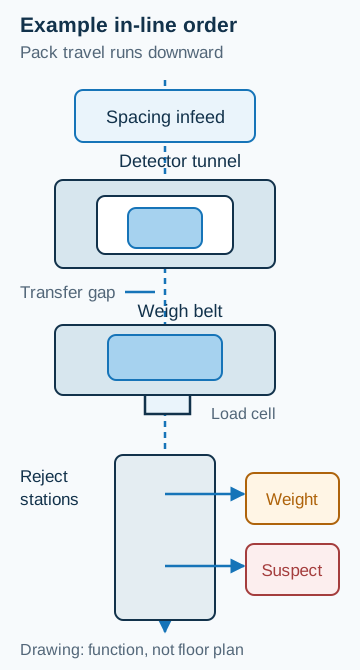
Example detector-first arrangement. The transfer gaps and separate weighing support require review as well as the station order. Schematic.
Annotate the proposed drawing with the pack direction, upstream discharge, detector aperture, transfer points, supported weigh length, reject positions, guarding and access for cleaning. Include the largest and least stable pack presentations. A drawing that only shows the overall machine footprint leaves those interfaces unresolved.
If metallized packaging makes final-pack inspection difficult, assess the actual wrapped product before moving inspection upstream. An upstream detector may avoid the packaging signal but leaves later handling outside its inspection boundary. Record that remaining contamination exposure and how the quality plan addresses it. Changing position is a control-design decision, not merely a way to make a detector learn routine succeed.
Preserve the weighing window through every transfer
The pack must have a usable interval on the weigh conveyor without support from adjacent conveyors. Review pack length in the direction of travel, flexible-pack sag, belt tracking, vibration, and the transfers into and out of the weighing section.
The following is a geometric screening calculation. It describes available fully supported travel time, before any allowance for entry disturbance, settling or signal processing:
t_supported = (B − L) / v, for B > L and constant belt speed.
Here, B is the supported weigh-belt length in millimetres, L is the pack length along travel in millimetres, and v is belt speed in millimetres per second. The result is in seconds. This relationship follows from the pack’s travel distance; it is not a checkweigher accuracy specification.
Assumed worked example, prepared October 19, 2026: a rigid pack has L = 180 mm, the supported weigh length is B = 400 mm, and all relevant belts run at v = 400 mm/s. Then t_supported = (400 mm − 180 mm) / 400 mm/s = 0.55 s. These are teaching inputs, not OEM dimensions or a demonstrated operating point. The usable measurement interval is shorter once the actual machine’s settling requirements are included.
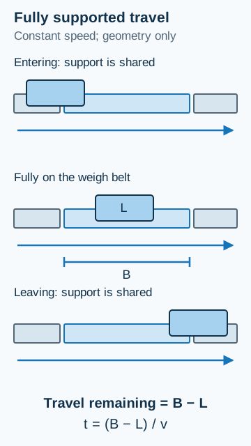
The fully supported interval comes from travel distance, not from the machine’s overall frame length. Geometry only; no accuracy is implied.
Threshold rule: if B − L ≤ 0 mm for the presented pack, choose a longer weigh conveyor or another validated weighing arrangement, because there is no positive travel interval with that pack wholly supported by this belt. Slowing the belt cannot create missing support length.
Also distinguish pack pitch from the weighing window. A nominally suitable pack can still arrive while the preceding pack occupies the measurement section. Check the actual spacing control and demonstrate close arrivals under the OEM’s permitted conditions. Do not infer allowable throughput from the calculation above. Transfer heights, speed changes and stop signals belong on the packaging line integration checklist.
Define reject destinations before selecting the mechanism
Write the disposition for each reject reason before deciding whether the combo needs a common device or separate devices. A weight exception and a metal alarm may need different investigation and release procedures even when both leave the same conveyor.
The Thompson in-motion checkweigher manual, version 15.3, printed page 58, documents configurations where a metal reject shares an underweight device, shares an overweight device, or uses its own device. These are controller options in that manual, not automatic features of every combo. Review the installed outputs and physical destinations together.
Swipe sideways to see the other columns. The first column stays visible.
| Proposed route | Decision to document | Dominant failure mode and prevention |
|---|---|---|
| Common reject device and collection point | Who investigates mixed reject reasons and authorizes disposition | A weight-only rework assumption is applied to a metal suspect; retain reason records and secure the entire mixed stream |
| Separate weight and metal destinations | How pack tracking associates each decision with the correct actuator | The right alarm removes a neighbouring pack; verify tracking and actual destination with marked challenge packs |
| Pack with both fault reasons | Which route takes priority and how both reasons remain recorded | Weight disposition overrides contamination containment; explicitly define and demonstrate the priority logic |
| Missing reject confirmation or failed utility | What stops, what remains on the conveyor and what production is held | The controller reports a reject but the pack stays on line; verify the defined fault response |
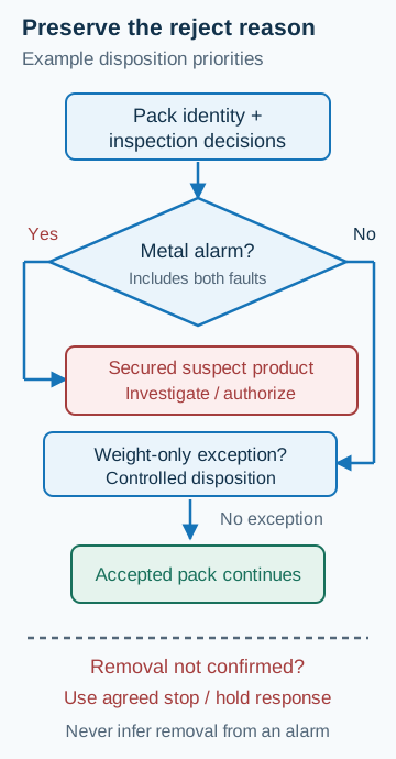
Illustrative disposition logic to specify with the integrator and quality team. Physical hardware may use common or separate reject devices.
Choose the actuator against the actual pack: its stability, mass distribution, surface, travel speed and behaviour on impact. An actuator cycling successfully without product does not show that a soft pouch, tall tray or sliding carton reaches the bin. Check clearance for the diverted pack and access without bypassing guards.
Keep detection, actuation and confirmation as separate observations in the acceptance record. Include bin access, a blocked destination, utility loss and restart behaviour wherever those functions form part of the agreed design. The Safeline guide preview, section 1.2, describes lockable collection and reject confirmation; it supports checking actual removal rather than relying on an alarm alone.
Verify product effect with the actual metallized film
Metallized film is a product-and-pack test condition, not an automatic exclusion and not a guarantee of compatibility. Keep it distinct from an aluminium-foil pack when assessing detection coverage.
LOMA’s difficult-product setup note identifies salt, moisture, temperature and metalized packaging as contributors to a large product signal. Reducing sensitivity can reduce detection performance. Consequently, a quieter reject counter after a setting change does not establish that the specified contaminants remain detectable.
Safeline’s guide preview, sections 1.2 and 1.5, includes metallized-film products within its balanced-coil application description but identifies aluminium foil as a different limitation. Its ferrous-in-foil discussion restricts coverage to ferrous and magnetic stainless contamination. Do not interpret that alternative as equivalent coverage for non-ferrous and non-magnetic stainless contaminants.
For the trial, identify the film construction, product recipe and temperature condition, pack orientation, approved challenge materials and their positions, aperture configuration and production presentation. Retain successful detection and removal results together. A film, temperature or product change should prompt review of the validated setup under the site’s procedure. Use the film and machine compatibility guide to keep the material specification attached to the machine trial.
Count the cost of containment and changeover
The hidden cost of a combo is not only its installed footprint. Common reject collection can add investigation and disposal work because suspect metal rejects cannot simply follow a weight-only rework assumption. Separate paths add components, cleaning access and verification tasks. A shared frame can also make access or repair of one function interrupt both.
Build the operating comparison from recorded tasks: product lost in changeover challenges, time spent restoring recipes, clearing bins, investigating false rejects and restarting after a failed check. Record who owns each task and which production remains available for containment. These are site measurements to collect, not generic savings percentages. The format changeover checklist helps include inspection recipes and restart checks in that cost record.
Use an acceptance record that follows the pack
Acceptance should connect each challenged pack to an inspection result, physical destination and restart decision. Agree the conditions in the FAT and SAT guide before the trial.
Swipe sideways to see the other columns. The first column stays visible.
| Record field | What to enter |
|---|---|
| Product and packaging | Recipe, lot, film construction, temperature condition and pack presentation |
| Installed arrangement | Drawing revision, detector position, weighing transfers, tracking and reject devices |
| Challenge identity | Approved weight reference or metal test piece, placement and marked pack identity |
| Inspection result | Weight decision, detection event and all applicable reject reasons |
| Removal result | Actuator response, confirmation and actual secured destination |
| Fault and recovery | Agreed fault tested, stop/hold response, affected product and authorized restart |
Resolve an unexplained mismatch before treating the line as accepted. The parent materials and inspection section maps the adjacent material and inspection decisions.
Method and sources
Reviewed October 19, 2026. The linked LOMA datasheet, Thompson manual and Safeline preview support the illustrated arrangement, reject options and stated detection limits. The LOMA setup note supports the product-effect discussion. The travel calculation and decision records are editorial engineering aids with explicit assumptions. Actual sensitivity, weight limits, permitted spacing and verification intervals must come from the applicable machine documentation and approved site plan.
Update history
- : First published.
- : Added a manual-based combo layout review, reject-routing checklist and assumed weigh-window calculation.
Next steps
Checkweighers vs. Metal Detectors: Different Inspection Jobs
A checkweigher verifies package weight and a metal detector controls metal contamination. See why one cannot replace the other and how to plan rejects and records.
Read guide
Packaging Line Integration Checklist: Interfaces to Confirm Before Ordering
Checklist of mechanical, electrical, signal, communication, safety and utility interfaces to settle before ordering a machine for a packaging line.
Read guide
FAT vs. SAT for Packaging Equipment: Defining Acceptance Criteria
Compare factory and site acceptance tests for packaging machines, and learn how to write acceptance criteria that both buyer and supplier can verify.
Read guide