
Container Closure Integrity Testing (CCIT): Deterministic vs Probabilistic Method Selection
Compare vacuum decay, HVLD, laser headspace, dye ingress and bubble testing against package rigidity, liquid conductivity, headspace and defect coverage.
Choose a CCIT method by the contents, package materials, headspace and defect locations it can evaluate. For conductive liquid in a suitable container, compare vacuum decay with HVLD; for a dry product with accessible headspace, consider vacuum decay or laser headspace. Confirm the shortlist with intact and defective controls in the intended product–package configuration.
Applies to: Method selection for sterile pharmaceutical product–package systems, including vials and prefilled syringes, with conditional comparisons for flexible and laminate packs.

Container closure integrity testing evaluates the barrier formed by a container and its closures. Choose the test by the physical signal the filled package can produce, then demonstrate that relevant defects are detectable under the intended conditions.
For a liquid-filled vial, that means comparing gas or vapor escape with an electrical leak path. For a lyophilized vial, the available gas headspace becomes another useful measurement route. For a syringe or flexible pack, movement and access to the relevant closure locations can change the choice again.
Use the comparison below to build a shortlist before specifying an instrument. The materials and inspection hub connects this decision with film compatibility and other package checks; packaging inspection equipment types separates integrity testing from weight, contamination and visual inspection.
Deterministic versus probabilistic CCIT
Deterministic methods measure a physical phenomenon that can be controlled and monitored. Probabilistic methods depend on a sequence of events, such as a tracer entering a defect and then being detected. The distinction helps explain method behavior, but the application still determines whether the test is suitable.
Vacuum decay, high-voltage leak detection (HVLD) and laser headspace analysis belong to the deterministic family. Dye ingress and bubble emission belong to the probabilistic family. Don Singer’s 2014 FDA/PQRI presentation on sterile-product package integrity illustrates this classification; USP chapter <1207.2>, Package Integrity Leak Test Technologies, addresses selection and use of leak-test technologies.
Swipe sideways to see the other columns. The first column stays visible.
| Method | Signal or event | Contents and package prerequisites | Interference to investigate | Key validation question |
|---|---|---|---|---|
| Vacuum decay — deterministic | Pressure rises around the package as gas or vapor escapes | Package fits an appropriate chamber; contents and geometry support the pressure challenge | Product in the leak path; flexible or movable components | Can relevant defects be distinguished from intact packages under the selected conditions? |
| HVLD — deterministic | Electrical response changes at a conductive breach | Suitable conductive liquid and comparatively low-conductivity container material | Inadequate liquid coverage, wall geometry, unsuitable conductivity | Does the setup detect defects at each relevant location with the actual fill? |
| Laser headspace — deterministic | Optical measurement of headspace gas properties | Measurable gas space and an accessible optical path | Obstructed light path; unsuitable initial gas state or observation interval | Does the protocol produce a detectable gas change for the leaks of concern? |
| Dye ingress — probabilistic | Tracer liquid enters and is detected | Package and contents compatible with the challenge and readout | Product blocking the leak path; opaque or colored fill interfering with the readout | Can the challenge and readout reliably distinguish leaking samples? |
| Bubble emission — probabilistic | Escaping gas produces observable bubbles | Package and test arrangement support gas escape and observation | Failure to form or observe bubbles under the chosen conditions | Are the relevant leaks observable in this configuration? |
Keep three separate questions in the comparison: What is measured? How is the result classified? What happens to the sample? An instrument can measure pressure or current and report a pass/fail decision. That does not make the measurement probabilistic. Conversely, an instrumental dye readout does not remove the uncertain transport events that precede detection.
Destructive versus nondestructive testing is a separate choice. Establish whether the complete procedure leaves the product and package suitable for their intended subsequent use. A deterministic label alone does not settle that question or guarantee a direct leak-rate measurement.
Vacuum decay vs high voltage leak detection
Compare vacuum decay and HVLD when a liquid-filled package can support both a pressure challenge and an electrical leak path. Their different signals make formulation, fill level and defect position central to the decision.
Vacuum decay: measure outside the package
Vacuum decay places the package inside an evacuated chamber and monitors chamber pressure. Gas leaving the package, or liquid volatilizing at a leak, can cause a pressure rise. The public scope of ASTM F2338-24 includes rigid and flexible nonporous packages and describes comparison with intact and leaking controls to establish acceptance criteria.
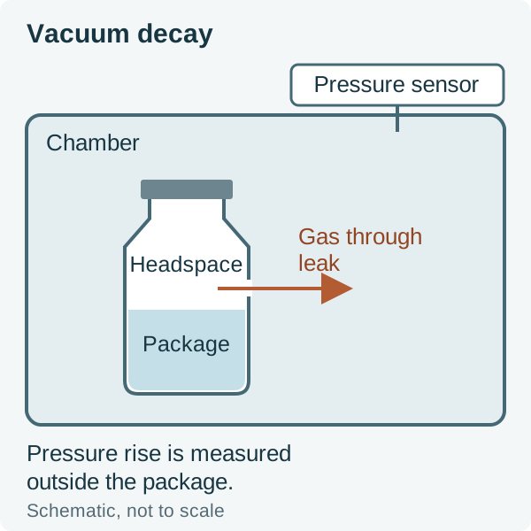
The practical question is whether the intended product can produce a detectable escape signal at the defect. A dry, open defect and a defect occupied by the formulation can behave differently. ASTM F2338-24 describes evaluating liquid-plugged leaks at chamber pressures below the liquid’s vaporization pressure. That makes formulation behavior and the selected pressure conditions part of method development. Include the actual fill and relevant defect conditions in feasibility work. For flexible packages and syringes with movable components, also evaluate how the fixture controls movement during the pressure challenge.
HVLD: establish the electrical path
HVLD senses an electrical change associated with a conductive breach. The described approach requires a conductive liquid within a suitable, relatively nonconductive container. The liquid must participate in the path being assessed; container wall geometry and the location of the defect also affect the response.
PTI’s Glass & Plastic Vials: HVLD application note identifies conductivity, fill level and wall geometry as application variables. Treat a change in fill or container geometry as a reason to revisit coverage. A setup that detects a body-wall defect does not, by itself, establish detection at the shoulder, neck or closure interface.

If the package contains a dry product without the required conductive liquid path, eliminate this HVLD approach from the shortlist. For a liquid-filled package, characterize conductivity and coverage instead of inferring them from the product’s appearance.
Protein and viscous fills: challenge the masking risk
PTI describes viscous or protein-containing formulations masking microdefects during pressure-based tests. The useful response is to test that possibility with the intended formulation and defined defective controls. If a pressure test loses the required discrimination, evaluate an electrical method where the liquid and container meet its prerequisites.
This is a conditional selection step. A protein-containing formulation does not automatically determine the method: the behavior of the actual leak path matters. Keep vacuum decay in consideration where formulation-aware development preserves the required discrimination. Evaluate HVLD with the actual conductive fill, relevant liquid contact and container geometry; include product condition in both evaluations.
When laser headspace fits
Consider laser headspace analysis when the sealed package provides a measurable gas space and a usable optical path. It is especially relevant to a lyophilized vial whose gas space can be examined through the container wall.
Laser headspace analysis measures gas concentration through optical absorption. LIGHTHOUSE Instruments’ Test Method Development for a Container Closure Integrity Test Using Headspace Gas Ingress describes detecting a change in gas composition caused by leakage. For a suitable modified headspace, oxygen entering from the surrounding air can provide that contrast.

Record the headspace volume, initial gas condition, optical access and interval between conditioning and measurement. These determine whether leakage can create a change the instrument can resolve. The time needed to take one reading is only one part of the complete test schedule.
If the headspace already contains ambient air, an oxygen reading alone cannot distinguish an intact package from one that has exchanged air through a leak. LIGHTHOUSE’s method-development study describes controlled tracer-gas conditioning as an alternative for this situation. Specify the gas contrast, conditioning and measurement interval together.
Include filled controls with defects exposed to the product. In LIGHTHOUSE’s study, submerged defects and protein-related blockage affected tracer-gas access to the headspace. An accessible optical path therefore answers only one part of the feasibility question; the challenge must also produce a detectable change inside a leaking package.
Where dye ingress and bubble methods fit
Evaluate probabilistic methods against the required detection task and their challenge conditions. For dye ingress, liquid must traverse the defect and the readout must detect it. For a bubble method, gas must escape and form bubbles that the arrangement can reveal.
Dye ingress commonly consumes samples through the challenge and subsequent examination. Product color, formulation blockage and the detection step can affect the outcome. The readout need not be exclusively visual: OFI’s Container and closure integrity testing describes quantifying methylene-blue ingress with UV/VIS analysis. Adding an instrument to the readout does not change the preceding tracer-transport mechanism.
The FDA’s February 2008 stability guidance discusses several possible integrity methods, including dye and bubble tests, and emphasizes validation and compatibility with the specific product. It also distinguishes integrity testing during stability from product sterility testing before release.
When comparing practical workload, include sample consumption, preparation, conditioning, readout and handling after the test. Those steps can change the resources needed even when the instrument measurement itself is brief. Keep the detection requirement fixed while comparing workflows.
Match the method to the package
Start with contents and materials, then check headspace, movement and defect coverage. The same nominal container family can require different test development after a change in fill, closure or laminate.
Swipe sideways to see the other columns. The first column stays visible.
| Product–package configuration | Initial candidates | Decisive feasibility checks |
|---|---|---|
| Rigid vial with aqueous liquid | Vacuum decay; HVLD where the electrical conditions fit | Actual formulation at the defect; conductivity; fill coverage; body, shoulder and closure locations |
| Liquid-filled prefilled syringe | Vacuum decay; HVLD where the liquid path is suitable | Plunger and other movable parts; fixture restraint; access to the relevant tip and plunger closure regions |
| Lyophilized vial | Vacuum decay; laser headspace where optical access is suitable | Product effects on the pressure response; gas space and initial gas state; optical path and timing |
| Flexible or laminate blister/pouch | Vacuum decay where the package and fixture are suitable; other routes only after their prerequisites are met | Laminate construction; flexibility; contents; seal access; optical and electrical properties |
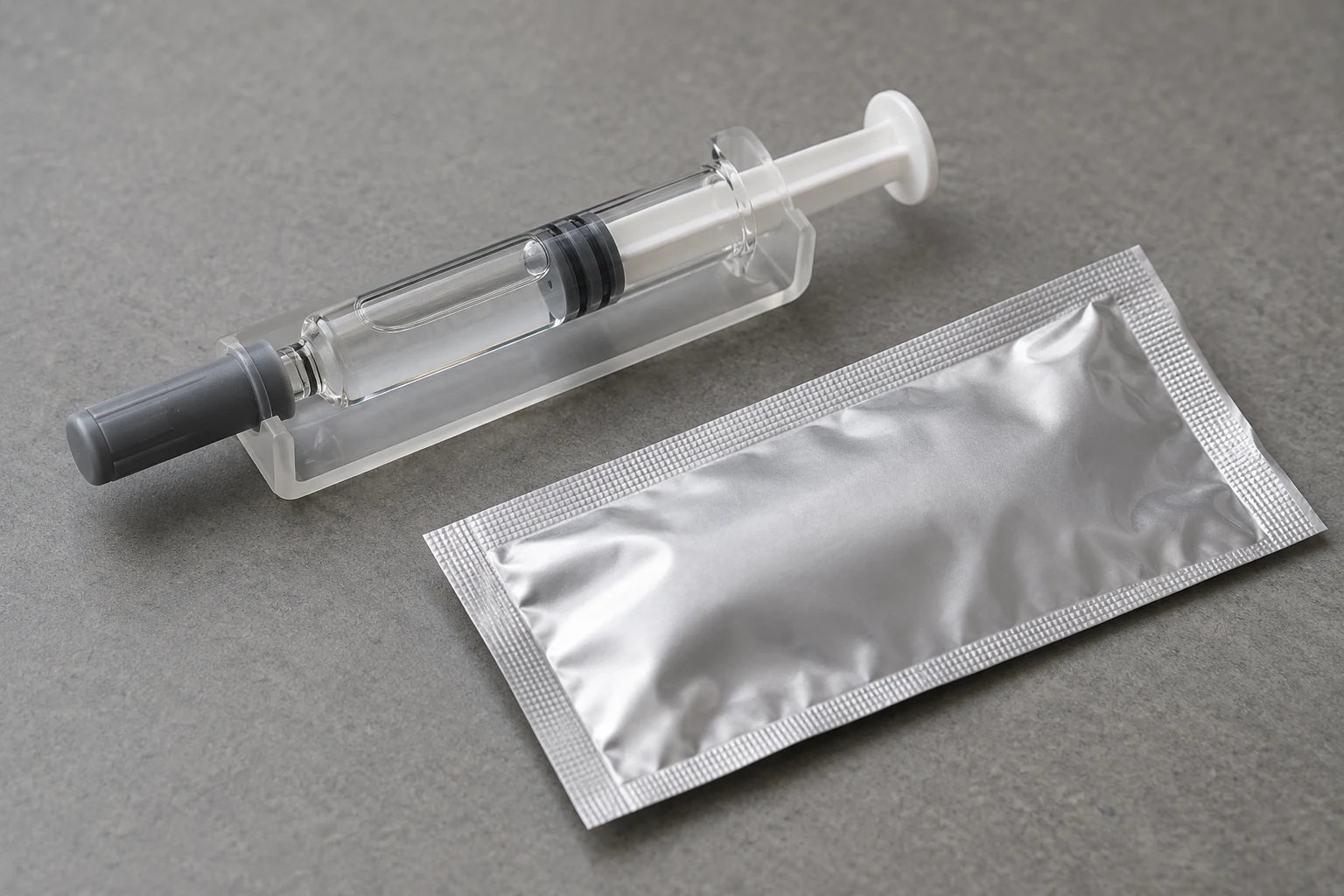
Two useful exclusions follow from the measurement prerequisites: dry contents lack the conductive liquid path described for HVLD, and opaque foil across the proposed light path prevents optical headspace access. These physical checks help narrow the options before method development.
For a flexible pack, identify whether the laminate is nonporous and how its shape changes under the intended challenge. For a syringe, document the assembled components and the positions that the test must evaluate. Record the configuration at the same level of detail as the product formulation.
Ordinary tablet blister selection also involves forming and sealing decisions. Use the blister packaging machine guide for those equipment questions, and establish the product’s barrier requirements before applying a sterile-product integrity program.
Verify the shortlist before specifying equipment
The selection is complete when application evidence supports the method for the intended product–package configuration. Equipment qualification establishes instrument performance; method validation establishes whether that performance answers the package integrity question.
Build the comparison around the same required detection capability and relevant defect locations. Include intact negative controls and defective positive controls whose characteristics are documented. Evaluate whether each candidate separates those populations across the configurations the method is intended to cover.
Document both the defect geometry and its behavior in the filled package. LIGHTHOUSE’s study distinguishes defined artificial paths, such as capillaries, from irregular closure-interface defects whose paths vary with the assembly. Treat nominal hole diameter, measured leak rate and the instrument’s detection limit as different descriptors. Relate the selected controls and acceptance criterion to the product’s barrier requirement rather than treating any one descriptor as a universal limit.
For vacuum decay, investigate formulation effects and package movement. For HVLD, challenge liquid coverage, conductivity and geometry. For headspace, evaluate gas state, optical access and timing. For dye or bubble methods, examine both the transport event and the ability to detect its outcome. Changing a fixture or fill condition can change the evidence needed for a method transfer.
Separate detection from cause investigation. A failed integrity result starts a product and packaging investigation; it does not identify the sealing-process cause on its own. The seal defect investigation guide provides a framework for organizing samples, locations and process evidence. If equipment procurement follows, distinguish installation and acceptance checks from the application study using the FAT versus SAT guide.
Product–package method-selection checklist
Prepare one configuration record for each combination the method must cover. Use these inputs to brief the testing team and compare feasibility proposals on the same basis:
- Identify the container, material, dimensions and all closure components, including relevant syringe components or laminate layers.
- Describe the contents: liquid, semi-liquid or dry product; record conductivity where electrical testing is a candidate.
- Record viscosity and any product behavior that could obscure a defect during the challenge.
- Record fill level, headspace volume and gas condition, and identify the proposed optical path for headspace analysis.
- Identify flexible walls, movable components and how the proposed fixture will control them.
- Map the relevant leak locations and identify how the method will challenge each one.
- State the required detection capability and the product-specific acceptance basis, with the units and conditions used to define them.
- Describe intact and defective controls, including how defects are characterized and presented to the test.
- Define the intended use: package development, a manufacturing check or stability evaluation, together with relevant conditioning and time points.
- Record sample consumption, preparation, handling and whether further use of tested samples is intended.
- Define the evidence needed for changes in formulation, fill, closure, package material or test fixture.
The resulting shortlist should say which method is feasible, which physical requirement supports it and which application study will confirm it. That gives packaging and quality teams a concrete basis for choosing CCIT equipment and planning validation.
References
- Container and Closure System Integrity Testing in Lieu of Sterility Testing as a Component of the Stability Protocol for Sterile Products (February 2008) — FDA
- ASTM F2338-24 — Nondestructive Detection of Leaks in Packages by Vacuum Decay Method: scope and significance — ASTM International
- USP <1207.2> — Package Integrity Leak Test Technologies: introduction — United States Pharmacopeia
- Benefits of Technology (September 2014 conference presentation, slides 14–15 on package integrity methods) — Don Singer, FDA/PQRI conference
- Glass & Plastic Vials: HVLD — application note — PTI
- Test Method Development for a Container Closure Integrity Test Using Headspace Gas Ingress — LIGHTHOUSE Instruments
- Container and closure integrity testing — headspace and dye-ingress workflows — OFI
Update history
- : First published.
- : Added method comparison, package matching and a product–package preparation checklist.
Next steps

Packaging Inspection Equipment: Match the Inspection Job
Match checkweighers, metal detectors, X-ray, vision and leak tests to packaging defects, then plan inspection positions, samples and rejection evidence.
Read guide
Packaging Seal Defects: An Evidence-Based Investigation Checklist
Investigate packaging seal defects by containing suspect product, collecting evidence, testing with agreed methods and changing one variable at a time.
Read guide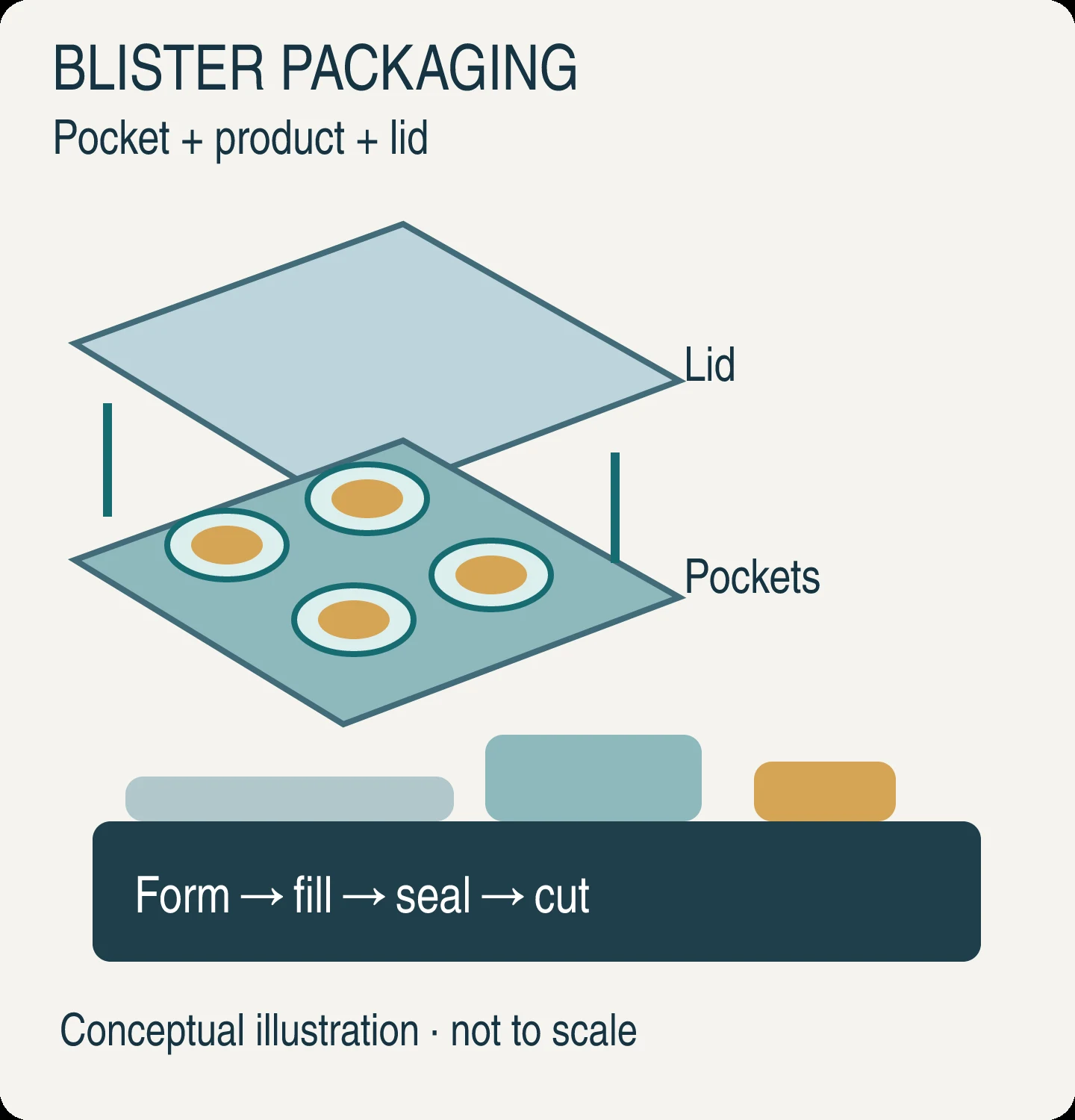
Blister Packaging Machines: Types and Supplier Questions
Compare blister machine workflows, forming routes and quote boundaries, with a practical checklist for tablet, food and pharmaceutical packaging projects.
Read guide